
Concept explainers
Videos
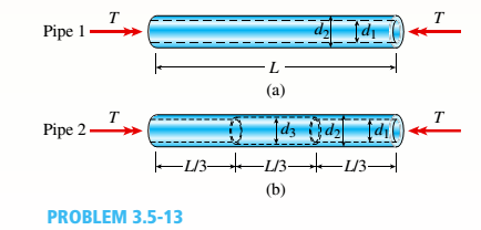
Two circular aluminum pipes of equal length L = 24 in. arc loaded by torsional moments T (sec figure). Pipe I has outside and inside diameters d2= 3 in. and L2, = 2.5 in., respectively. Pipe 2 has a constant outer diameter of d2along its entire length L and an inner diameter of d1but has an increased inner diameter of d3= 2.65 in. over the middle third.
Assume that E = 10,400 ksi, u = 0.33, and allowable shear stress ra= 6500 psi.
- Find the maximum acceptable torques that can be applied to Pipe 1; repeat for Pipe 2.
(a)
The maximum acceptable torques for pipe (1).
The maximum acceptable torques for pipe (2).
Answer to Problem 3.5.13P
Maximum acceptable torques for pipe (1) is =
Maximum acceptable torques for pipe (2) is =
Explanation of Solution
Given information:
The following figure shows the free body diagram of pipe 1:
Figure-(1) shows the diagram of two pipes:
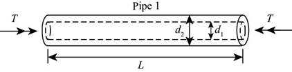
Figure-(1)
The following figure shows the free body diagram of pipe 2:
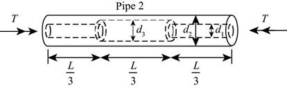
Figure-(2)
The length of pipe is
Write the expression for polar moment of inertia for pipe (1)
Here, the polar moment of inertia is
Write the expression for maximum torque for pipe (1)
Here, acceptable shear stress is
Write the expression for polar moment of inertia for pipe (2)
Here, the polar moment of inertia is
Write the expression for maximum torque for pipe (2)
Here, acceptable shear stress is
Calculation:
Substitute,
Substitute
Substitute,
Substitute
Conclusion:
Maximum acceptable torques for pipe (1) is =
Maximum acceptable torques for pipe (2) is =
(b)
The maximum acceptable length of the middle segment.
Answer to Problem 3.5.13P
The maximum acceptable length of the middle segment.
Explanation of Solution
Given information:
Maximum twist of pipe (2) cannot exceed
Write the expression for the angle of twist for pipe (1).
Here the angle of twist is
Write the expression for total angle of twist for pipe (2)
Here, the total angle of twist is
Write the expression for the length of the segment
Write expression for the angle of twist in the section
Write expression for the angle of twist in the section
Write expression for the angle of twist in the section
Substitute
Write the expression for relation between
Calculation:
Substitute
Substitute
Substitute
Conclusion:
The maximum acceptable length of the middle segment is =
(c)
The inner diameter for the given parameters.
Answer to Problem 3.5.13P
The inner diameter for the given parameters is =
Explanation of Solution
Given information:
the maximum torque carried by pipe (2) is
Write the expression for allowable torque.
Here, the allowable torque is
Substitute
Calculation:
Substitute
Conclusion:
The inner diameter for the given parameters is
(c)
Applied torque on pipe (1)
Maximum twist of pipe (1)
Answer to Problem 3.5.13P
Applied torque on pipe (1) is =
Applied torque on pipe (2) is =
Maximum twist of pipe (1) is =
Explanation of Solution
Write the expression for maximum shear strain.
Here, maximum shear strain is
Write the expression for maximum shear stress.
Here, the maximum shear stress is
Write the expression for shear modulus of elasticity.
Write the expression for maximum torque for pipe (1)
Write the expression for maximum angle of twist for pipe (1)
Maximum angle of twist in pipe (1) is
Calculation:
Substitute
Substitute
Substitute
Substitute
Substitute
Substitute
Conclusion:
Applied torque on pipe (1) is =
Applied torque on pipe (2) is =
Maximum twist of pipe (1) is =
Want to see more full solutions like this?
Chapter 3 Solutions
Bundle: Mechanics Of Materials, Loose-leaf Version, 9th + Mindtap Engineering, 1 Term (6 Months) Printed Access Card


- DO NOT COPY SOLUTION- will report The differential equation of a cruise control system is provided by the following equation: Find the closed loop transfer function with respect to the reference velocity (vr) . a. Find the poles of the closed loop transfer function for different values of K. How does the poles move as you change K? b. Find the step response for different values of K and plot in MATLAB. What can you observe?arrow_forwarda box shaped barge 37m long, 6.4 m beam, floats at an even keel draught of 2.5 m in water density 1.025 kg/m3. If a mass is added and the vessel moves into water density 1000 kg/m3, determine the magnitude of this mass if the fore end and aft end draughts are 2.4m and 3.8m respectively.arrow_forwarda ship 125m long and 17.5m beam floats in seawater of 1.025 t/m3 at a draught of 8m. the waterplane coefficient is 0.83, block coefficient 0.759 and midship section area coefficient 0.98. calculate i) prismatic coefficient ii) TPC iii) change in mean draught if the vessel moves into water of 1.016 t/m3arrow_forward
- c. For the given transfer function, find tp, ts, tr, Mp . Plot the resulting step response. G(s) = 40/(s^2 + 4s + 40) handplot only, and solve for eacharrow_forwardA ship of 9000 tonne displacement floats in fresh water of 1.000 t/m3 at a draught 50 mm below the sea water line. The waterplane area is 1650 m2. Calculate the mass of cargo which must be added so that when entering seawater of 1.025 t/m3 it floats at the seawater line.arrow_forwardA ship of 15000 tonne displacement floats at a draught of 7 metres in water of 1.000t/cub. Metre.It is required to load the maximum amount of oil to give the ship a draught of 7.0 metre in seawater ofdensity 1.025 t/cub.metre. If the waterplane area is 2150 square metre, calculate the massof oil requiredarrow_forward
- A ship of 8000 tonne displacement floats in seawater of 1.025 t/m3 and has a TPC of 14. The vessel moves into fresh water of 1.000 t/m3 and loads 300 tonne of oil fuel. Calculate the change in mean draught.arrow_forwardAuto Controls DONT COPY ANSWERS - will report Perform the partial fraction expansion of the following transfer function and find the impulse response: G(s) = (s/2 + 5/3) / (s^2 + 4s + 6) G(s) =( 6s^2 + 50) / (s+3)(s^2 +4)arrow_forwardI submitted the below question and received the answer i copied into this question as well. Im unsure if it is correct, so looking for a checkover. i am stuck on the part tan-1 (0.05) = 0.04996 radians. Just unsure where the value for the radians came from. Just need to know how they got that answer and how it is correct before moving on to the next part. If any of the below information is wrong, please feel free to give me a new answer or an entire new explanation. An Inclining experiment done on a ship thats 6500 t, a mass of 30t was moved 6.0 m transvesly causing a 30 cm deflection in a 6m pendulum, calculate the transverse meta centre height. Here is the step-by-step explanation: Given: Displacement of the ship (W) = 6500 tonnes = 6500×1000=6,500,000kg Mass moved transversely (w) = 30 tonnes=30×1000=30,000kg The transverse shift of mass (d) = 6.0 meters Pendulum length (L) = 6.0 meters Pendulum deflection (x) = 30 cm = 0.30 meters Step 1: Formula for Metacentric Height…arrow_forward
 Mechanics of Materials (MindTap Course List)Mechanical EngineeringISBN:9781337093347Author:Barry J. Goodno, James M. GerePublisher:Cengage Learning