
Applied Statics and Strength of Materials (6th Edition)
6th Edition
ISBN: 9780133840544
Author: George F. Limbrunner, Craig D'Allaird, Leonard Spiegel
Publisher: PEARSON
expand_more
expand_more
format_list_bulleted
Videos
Textbook Question
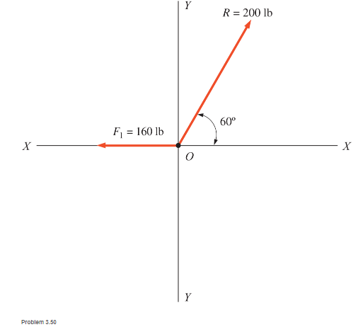
Chapter 3, Problem 3.50SP
The resultant and one-component force of a two-force concurrent force system are shown. Compute the other component force F2 (not shown) that would be required. Determine magnitude, direction, and sense.
Expert Solution & Answer

Learn your wayIncludes step-by-step video

schedule04:38
Students have asked these similar questions
Determine the magnitude and direction of theresultant force R for the two coplanar forces shown.• Draw the force triangle.• Use the triangle rule and the Law of Sines and theLaw of Cosines to solve the problem.Do not resolve the forces into components to find theresultant force.
What is the resultant force if the forces of 40N and 60N are acting at an angle of 60 degrees to each other?
Use a vector diagram.
1. Draw the vector diagram with resultant vector
2. Solve the magnitude of resultantforce
3. Solve the direction of resultantforce
2.
The tension in both ropes is 70 lb. Find the magnitude and direction of the resultant force at B.
5 ft
7 ft
5 ft.
7 ft.
8 ft
4 ft
5 ft
Chapter 3 Solutions
Applied Statics and Strength of Materials (6th Edition)
Ch. 3 - through 3.3 Determine the magnitude, direction,...Ch. 3 - Determine the magnitude, direction, and sense of...Ch. 3 - Determine the magnitude, direction, and sense of...Ch. 3 - Solve Problem 3.1 through 3.3 using the method of...Ch. 3 - Solve Problem 3.1 through 3.3 using the method of...Ch. 3 - through 3.6 Solve Problem 3.1 through 3.3 using...Ch. 3 - The 150-lb force shown is the resultant of two...Ch. 3 - Find the resultant force P exerted on the tree.Ch. 3 - Find the resultant force R exerted on the pole.Ch. 3 - Calculate the resultant force on the screw eye....
Ch. 3 - Determine the resultant of the coplanar concurrent...Ch. 3 - Use the parallelogram law to find the following...Ch. 3 - Prob. 3.13PCh. 3 - Determine the resultant of the coplanar concurrent...Ch. 3 - The resultant of the concurrent force system shown...Ch. 3 - Three force of 900 lb, 1000 lb, and 600 lb are...Ch. 3 - The four forces shown hade parallel lines of...Ch. 3 - Three coplanar concurrent forces act as shown. a....Ch. 3 - Four coplanar concurrent forces act as shown a....Ch. 3 - Determine the resultant of the four forces of...Ch. 3 - For the concrete wall and footing shown: a....Ch. 3 - Calculate the moment of the 550-lb force about...Ch. 3 - In Problem 3.22 , calculate the moment about point...Ch. 3 - Compute the moment about point A for the linkage...Ch. 3 - Compute the moment of the force F about point A...Ch. 3 - Determine the magnitude of the resultant of the...Ch. 3 - Determine the magnitude of the resultant of the...Ch. 3 - Determine the magnitude of the resultant of the...Ch. 3 - Determine the magnitude of the resultant of the...Ch. 3 - Determine the resultant and its location for the...Ch. 3 - Compute the magnitude, sense, and location of the...Ch. 3 - Compute the magnitude, sense, and location of the...Ch. 3 - Compute the magnitude and location of the...Ch. 3 - Determine the magnitude and location of the...Ch. 3 - Fresh water is impounded behind a dam to a height...Ch. 3 - Determine the magnitude and location of the...Ch. 3 - Determine the magnitude and location of the...Ch. 3 - Compute the magnitude and direction of the...Ch. 3 - Compute the magnitude and direction of the...Ch. 3 - Compute the magnitude and direction of the...Ch. 3 - A body is subjected to the following three...Ch. 3 - Determine the magnitude, direction, and sense of...Ch. 3 - Determine the magnitude, direction, and sense of...Ch. 3 - Determine the resultant of the load system shown....Ch. 3 - For the concrete structure shown, determine the...Ch. 3 - For the following computer problems, any...Ch. 3 - For the following computer problems, any...Ch. 3 - For the following computer problems, any...Ch. 3 - 3.49 Determine the magnitude, direction, and sense...Ch. 3 - The resultant and one-component force of a...Ch. 3 - The resultant force of a concurrent force system...Ch. 3 - Determine the magnitudes of forces P1 and P2 such...Ch. 3 - The resultant force of a concurrent force system...Ch. 3 - A hockey puck is acted on simultaneously by two...Ch. 3 - Determine the resultant force for each of the...Ch. 3 - Determine the resultant force for each of the...Ch. 3 - The resultant of the three concurrent forces shown...Ch. 3 - The transmission tower shown is subjected to a...Ch. 3 - A gravity-type masonry dam, as shown, depends on...Ch. 3 - The transfomer (as shown) must be lifted...Ch. 3 - Refer to the diagram for Problem 3.60 /. Assume...Ch. 3 - The plastic barrel tent anchor of Problem 2.11...Ch. 3 - Calculate the moment of the forces shown with...Ch. 3 - Determine the magnitude and location of the...Ch. 3 - Determine the moment (about point A) of the appied...Ch. 3 - The lift force on the wing of an aircraft is...Ch. 3 - A beam is subjected to distributed loads as shown....Ch. 3 - For the concrete gravity wall shown, determine the...Ch. 3 - Fresh water is impounded to a height of 8 ft...Ch. 3 - Plank, 2 in. by 10 in. in cross section and 5 ft...Ch. 3 - a. Compute the moment (about point A) of the...Ch. 3 - Determine the resultant of the three forces acting...Ch. 3 - a. Calculate the moments about points A and B due...Ch. 3 - Determine the magnitude of F1 and F2 shown such...Ch. 3 - Calculate the magnitude, direction, and sense of...
Additional Engineering Textbook Solutions
Find more solutions based on key concepts
Convert a volume of 6.35 liters to cubic nneters.
Applied Fluid Mechanics (7th Edition)
The moment of force about point O.
Engineering Mechanics: Statics & Dynamics (14th Edition)
Determine the speed of the brick just before it leaves the surface at B, the distanced d from the wall to where...
Engineering Mechanics: Dynamics (14th Edition)
Determine the magnitude and coordinate direction angles of the resultant force of the two forces acting on the ...
INTERNATIONAL EDITION---Engineering Mechanics: Statics, 14th edition (SI unit)
What parts are included in the vehicle chassis?
Automotive Technology: Principles, Diagnosis, and Service (5th Edition)
Determine the resultant internal loadings acting on the cross sections at points F and G of the frame. Probs. 7...
Statics and Mechanics of Materials (5th Edition)
Knowledge Booster


Learn more about
Need a deep-dive on the concept behind this application? Look no further. Learn more about this topic, mechanical-engineering and related others by exploring similar questions and additional content below.Similar questions
- The force R is the resultant of P and 0. Determine Q and the angle .arrow_forwardThe magnitudes of the three forces are F1=1.6kN,F2=1.2kN and F3=1.0kN. Compute their resultant in the form (a) R=Rxi+Ryj+Rzk; and (b) R=R.arrow_forwardThe pole OB is subjected to the 6004b force at B. Determine (a) the rectangular components of the force; and (b) the angles between the force vector and the coordinate axes.arrow_forward
- Find the internal force systems acting on sections 1 and 2.arrow_forwardA 10-m steel pole is supported by a ball and socket joint at O and held by three cables, DE, DF, and DG. Note the following properties of the three tension forces acting on point D: Force DE = 250N, on the x-y plane Force DF = 300N, 8 = 15*, ¢ = 20° Force DG = (125i-125j - 125k) N 7.5m 10mm :arrow_forwardFind the representation of the force F, given that its magnitude 240N.arrow_forward
- For the distributed loading shown, find the equivalent resultant force and specify its location measured from point A, along AB, given: W1 = 260 lb/ft, W2 = 100 lb/ft, L1 = 9 ft, L2= 6 ft The magnitude of resultant force, FR is: (enter a positive number) FR = lbs The distance from point A in the positive X-direction is: d = ftarrow_forward. The resultant of the three forces shown is a counterclockwise couple of magnitude 150 lb·ft. Calculate the magnitudes of the forces.arrow_forwardFigure 5(a) shows a car seat installation robot. It does the job of three people lifting and installing the seat as shown in Figure 5(b). 8 = 70° and = 50°. The robot exerts the wrench resultant of the forces exerted by the three people. Determine this wrench resultant. Your answer must include the rectangular component (Cartesian) form of the resultant force, the magnitude of the moment collinear with this resultant force and the coordinates of point P on the y-z plane through which the resultant force acts. Figure 5(a) 40 N 50 N z 1 0.4 m (b) 0.3 m 0.5 m 30 Narrow_forward
- answer the following questions 1. Find the force F if the resultant forces pass through a 50 Ib point A 75 Ib 2. Find the equivalent force 3. Specify where resultant 's line of action intersect member AB measured from point A 4. Specify where resultant 's line of action intersect member BC measured from point B 30° 3 ft 3 ft 4 ft 30° 50 Ib 75 Ib 1 Add filearrow_forwardparts d,e,farrow_forwardCalculate the magnitude of the resultant for the force system shown in figure below. 600N SOON 407 30' 400N 300Narrow_forward
arrow_back_ios
SEE MORE QUESTIONS
arrow_forward_ios
Recommended textbooks for you
 International Edition---engineering Mechanics: St...Mechanical EngineeringISBN:9781305501607Author:Andrew Pytel And Jaan KiusalaasPublisher:CENGAGE L
International Edition---engineering Mechanics: St...
Mechanical Engineering
ISBN:9781305501607
Author:Andrew Pytel And Jaan Kiusalaas
Publisher:CENGAGE L
How to balance a see saw using moments example problem; Author: Engineer4Free;https://www.youtube.com/watch?v=d7tX37j-iHU;License: Standard Youtube License