With the same transformer banks as in Problem 3.47, Figure 3.41 shows the oneline diagram of a generator, a step-up transformer bank, a transmission line, a stepown transformer bank, and an impedan load. The generator terminal voltage is 15 kV (line-to-line). (a) Draw the per-phase equivalent circuit, aounting for phase shifts for positive-sequence operation. (b) By choosing the line-to-neutral generator terminal voltage as the reference, determine the magnitudes of the generator current, transmiss ion-line current, load current, and line-to-line load voltage. Also, find the three-phase complex power delivered to the load.
With the same transformer banks as in Problem 3.47, Figure 3.41 shows the oneline diagram of a generator, a step-up transformer bank, a transmission line, a stepown transformer bank, and an impedan load. The generator terminal voltage is 15 kV (line-to-line). (a) Draw the per-phase equivalent circuit, aounting for phase shifts for positive-sequence operation. (b) By choosing the line-to-neutral generator terminal voltage as the reference, determine the magnitudes of the generator current, transmiss ion-line current, load current, and line-to-line load voltage. Also, find the three-phase complex power delivered to the load.
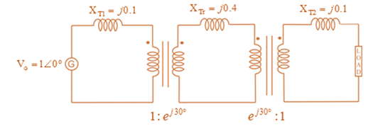
With the same transformer banks as in Problem 3.47, Figure 3.41 shows the oneline diagram of a generator, a step-up transformer bank, a transmission line, a stepown transformer bank, and an impedan load. The generator terminal voltage is 15 kV (line-to-line).
(a) Draw the per-phase equivalent circuit, aounting for phase shifts for positive-sequence operation.
(b) By choosing the line-to-neutral generator terminal voltage as the reference, determine the magnitudes of the generator current, transmiss ion-line current, load current, and line-to-line load voltage. Also, find the three-phase complex power delivered to the load.
6) For each independent source in this circuit calculate
the amount of power being supplied or the amount of
power being absorbed
+
6V
www
+3V-
www
20
ми
ми
352
0.5A
+
3V
In this experiment, we are going to use a 2N3904 BJT. Examine the data sheet for this device
carefully. In particular, make a note of the current gain (identified by hFE).
1. Obtain the curve trace for a "Darlington Pair" of Bipolar Junction Transistors. A Darlington
Pair consists of two transistors with the first BJT driving the base terminal of the second
transistor as shown in Figure 1 below.
A. Set up the primary sweep voltages for V1 the same as shown in the lecture notes (see
the Darlington pair IV curve).
B. Set up the secondary sweep currents for 11 to be an order of magnitude smaller than
for the single BJT. In the Sweep Type box choose linear and enter the following 3
values: Start Value: 0, End Value: 8u and Increment: 1u (see lecture notes).
C. Describe the primary differences you observe between the single BJT Curve Trace and
that of the Darlington Pair. Discuss what might cause each difference.
Q1
11
Q2
V1
Q2N3904
Figure 1. A Darlington Pair of 2N3904 transistors in a…
2. Using the IV plots shown in Fig. 3 (and found in the reintroduction to PSpice) design a BJT
biasing circuit that results in the following parameters: VCE = 2 Vand ig = 40 μA. We
also require the power supply to be fixed at 5 Volts (this is where the load line intercepts
the iB =ic = 0 line). You may use the circuit shown in Example 1. Note that all resistor
values in Example 1 must be recalculated. Your solution for the base to ground and base
to collector resistors may not be unique.
Chapter 3 Solutions
MindTap Engineering, 1 term (6 months) Printed Access Card for Glover/Overbye/Sarma's Power System Analysis and Design, 6th
Need a deep-dive on the concept behind this application? Look no further. Learn more about this topic, electrical-engineering and related others by exploring similar questions and additional content below.
How does a Transformer work - Working Principle electrical engineering; Author: The Engineering Mindset;https://www.youtube.com/watch?v=UchitHGF4n8;License: Standard Youtube License


 Power System Analysis and Design (MindTap Course ...Electrical EngineeringISBN:9781305632134Author:J. Duncan Glover, Thomas Overbye, Mulukutla S. SarmaPublisher:Cengage Learning