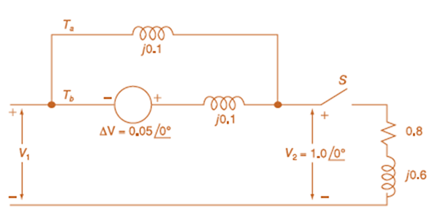
The per-unit equivalent circuit of two transformers T a and T b connected in parallel, with the same nominal voltage ratio and the same reactan of 0.1 per unit on the same base, is shown in Figure 3.43. Transformer T b has a voltage-magnitude step-up toward the load of 1.05 times that of T a (that is, the tap on the secondary winding of T b is set to 1.05). The load is represented by 0.8 + j 0.6 per unit at a voltage V 2 = 1 .0 / 0 ° per unit. Determine the complex power in per unit transmitted to the load through each transformer, comment on how the transformers share the real and reactive powers.
The per-unit equivalent circuit of two transformers T a and T b connected in parallel, with the same nominal voltage ratio and the same reactan of 0.1 per unit on the same base, is shown in Figure 3.43. Transformer T b has a voltage-magnitude step-up toward the load of 1.05 times that of T a (that is, the tap on the secondary winding of T b is set to 1.05). The load is represented by 0.8 + j 0.6 per unit at a voltage V 2 = 1 .0 / 0 ° per unit. Determine the complex power in per unit transmitted to the load through each transformer, comment on how the transformers share the real and reactive powers.
Solution Summary: The author explains the complex power in per unit supplied to the load through each transformer and the process of sharing real and reactive powers by transformer.
The per-unit equivalent circuit of two transformers
T
a
and
T
b
connected in parallel, with the same nominal voltage ratio and the same reactan of 0.1 per unit on the same base, is shown in Figure 3.43. Transformer
T
b
has a voltage-magnitude step-up toward the load of 1.05 times that of
T
a
(that is, the tap on the secondary winding of
T
b
is set to 1.05). The load is represented by
0.8
+
j
0.6
per unit at a voltage
V
2
=
1
.0
/
0
°
per unit. Determine the complex power in per unit transmitted to the load through each transformer, comment on how the transformers share the real and reactive powers.
Can you rewrite the solution because it is
unclear?
AM
(+) = 8(1+0.5 cos 1000kt +0.5 ros 2000 thts)
=
cos 10000 πt.
8 cos wat + 4 cos wit + 4 cos Wat coswet.
J4000 t
j11000rt
$14+) = 45
jqooort
+4e
+ e
+ e
j 12000rt.
12000 kt
+ e
+e
+e
Le
jsoort
-; goon t
te
+e
Dcw>
= 885(W- 100007) + 8 IS (W-10000) -
USB
Can you rewrite the solution because it is
unclear?
Q2
AM
①(+) = 8 (1+0.5 cos 1000πt +0.5 ros 2000kt)
$4+) = 45
=
*cos 10000 πt.
8 cos wat + 4 cosat + 4 cos Wat coswet.
j1000016
+4e
-j10000πt j11000Rt
j gooort -j 9000 πt
+
e
+e
j sooort
te
+e
J11000 t
+ e
te
j 12000rt.
-J12000 kt
+ с
= 8th S(W- 100007) + 8 IS (W-10000)
<&(w) =
USB
-5-5
-4-5-4
b) Pc 2² = 64
PSB =
42
+ 4
2
Pt Pc+ PSB =
y = Pe
c) Puss =
PLSB =
= 32
4² = 8 w
32+ 8 =
× 100% = 140
(1)³×2×2
31
= 20%
x 2 = 3w
302
USB
4.5 5 5.6 6
ms Ac = 4 mi
= 0.5
mz Ac = 4
५
M2
=
=0.5
A. Draw the waveform for the following binary sequence using Bipolar RZ, Bipolar NRZ, and
Manchester code.
Data sequence= (00110100)
B. In a binary PCM system, the output signal-to-quantization ratio is to be hold to a minimum of
50 dB. If the message is a single tone with fm-5 kHz. Determine:
1) The number of required levels, and the corresponding output signal-to-quantizing noise ratio.
2) Minimum required system bandwidth.
Chapter 3 Solutions
MindTap Engineering, 1 term (6 months) Printed Access Card for Glover/Overbye/Sarma's Power System Analysis and Design, 6th
Need a deep-dive on the concept behind this application? Look no further. Learn more about this topic, electrical-engineering and related others by exploring similar questions and additional content below.


 Power System Analysis and Design (MindTap Course ...Electrical EngineeringISBN:9781305632134Author:J. Duncan Glover, Thomas Overbye, Mulukutla S. SarmaPublisher:Cengage Learning