
EBK ELECTRICAL ENGINEERING
7th Edition
ISBN: 8220106714201
Author: HAMBLEY
Publisher: YUZU
expand_more
expand_more
format_list_bulleted
Videos
Textbook Question
Chapter 3, Problem 3.24P
Find the equivalent capacitance for each of the circuits shown in Figure P3.24.
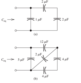
Figure P3.24
Expert Solution & Answer

Trending nowThis is a popular solution!

Learn your wayIncludes step-by-step video

schedule06:13
Students have asked these similar questions
Don't use ai to answer I will report you answer
Don't use ai to answer I will report you answer
type (o)
bT
S+αT
Profational controller
a = b = 5, T-La
|kp|
50
5+50
kp=20,50,70
② type (1)
bT
5(stat)
a=b=5,T= 1
✓ KT
5
SC5+5
kp=20, 50, 70
(Find Wny, ess for type (a) and (1))
Chapter 3 Solutions
EBK ELECTRICAL ENGINEERING
Ch. 3 - What is a dielectric material? Give two examples.Ch. 3 - Briefly discuss how current can flow “through” a...Ch. 3 - What current flows through an ideal capacitor if...Ch. 3 - Describe the internal construction of capacitors.Ch. 3 - A voltage of 50 V appears across a 10F capacitor....Ch. 3 - A 2000F capacitor, initially charged to 100V, is...Ch. 3 - A 5F Capacitor ischarged to 1000 V. Determine the...Ch. 3 - The voltage across a 10F capacitor is given by v...Ch. 3 - The voltage across a 1F capacitor is given by...Ch. 3 - Prior to t = 0, a 100F capacitance is uncharged...
Ch. 3 - The current through a 0.5F capacitor is shown in...Ch. 3 - Determine the capacitor voltage, power, and stored...Ch. 3 - A current given by i(t)=Imcos(t) flows through a...Ch. 3 - The current through a 3F capacitor is shown in...Ch. 3 - A constant (dc) current i(t)=3 mA flows into a 50F...Ch. 3 - The energy stored in a 2F capacitor is 200 J and...Ch. 3 - At t=t0 the voltage across a certain capacitance...Ch. 3 - An unusual capacitor has a capacitance that is a...Ch. 3 - For a resistor, what resistance corresponds to a...Ch. 3 - Suppose we have a very large capacitance (ideally,...Ch. 3 - We want to store sufficient energy in a 001-F...Ch. 3 - A 100F capacitor has a voltage given by v(t)=1010...Ch. 3 - How are capacitances combined in series and in...Ch. 3 - Find the equivalent capacitance for each of the...Ch. 3 - Find the equivalent capacitance between terminals...Ch. 3 - A network has a 5F capacitance in series with the...Ch. 3 - What are the minimum and maximum values of...Ch. 3 - Two initially uncharged capacitors C1=15F and...Ch. 3 - Suppose that we are designing a cardiac pacemaker...Ch. 3 - Suppose that we have two 100F capacitors One is...Ch. 3 - Determine the capacitance of a parallel-plate...Ch. 3 - A 100-pF capacitor is constructed of parallel...Ch. 3 - We have a parallel-plate capacitor with plates of...Ch. 3 - Suppose that we have a 1000-pF parallel-plate...Ch. 3 - Two 1F capacitors have an initial voltage of 100 V...Ch. 3 - Prob. 3.36PCh. 3 - Prob. 3.37PCh. 3 - A parallel-plate capacitor is used as a vibration...Ch. 3 - A 0.1F capacitor has a parasitic series resistance...Ch. 3 - Prob. 3.40PCh. 3 - Briefly discuss how inductors are constructed.Ch. 3 - The current flowing through an inductor is...Ch. 3 - If the current through an ideal inductor is...Ch. 3 - Briefly discuss the fluid-flow analogy for an...Ch. 3 - The current flowing through a 2-H inductance is...Ch. 3 - The current flowing through a 100-mH inductance is...Ch. 3 - The current flowing through a 2-H inductance is...Ch. 3 - The voltage across a 2-H inductance is shown in...Ch. 3 - The voltage across a 10 H inductance is given by...Ch. 3 - A 2-H inductance has i(0) = 0 and v(t)=texp(t) for...Ch. 3 - A constant voltage of 10V is applied to a 50H...Ch. 3 - At t = 0, the current flowing in a 05-H inductance...Ch. 3 - The current through a 100-mH inductance is given...Ch. 3 - Prior to t= 0, the current in a 2-H inductance is...Ch. 3 - At t= 0, a constant 5-V voltage source is applied...Ch. 3 - Prob. 3.56PCh. 3 - Al t= 5 s, the energy stored in a 2-H inductor is...Ch. 3 - What value of inductance (having zero initial...Ch. 3 - To what circuit element does a very large...Ch. 3 - The voltage across an inductance L is given by...Ch. 3 - Discuss how inductances are combined in series and...Ch. 3 - Determine the equivalent inductance for each of...Ch. 3 - Find the equivalent inductance for each of the...Ch. 3 - What is the maximum inductance that can be...Ch. 3 - Suppose we want to combine (in series or in...Ch. 3 - Prob. 3.66PCh. 3 - Two inductances L1=1H and L2=2H are connected in...Ch. 3 - A 10-mH inductor has a parasitic series resistance...Ch. 3 - Draw the equivalent circuit for a real inductor,...Ch. 3 - Suppose that the equivalent circuit shown in...Ch. 3 - Consider the circuit shown in Figure P3.71 in...Ch. 3 - The circuit shown in Figure P3.72 has...Ch. 3 - Describe briefly the physical basis for mutual...Ch. 3 - The mutually coupled inductances in Figure P3.74...Ch. 3 - Repeat Problem P3.74 with the dot placed at the...Ch. 3 - a. Derive an expression for the equivalent...Ch. 3 - Consider the parallel inductors shown in Figure...Ch. 3 - Consider the mutually coupled inductors shown in...Ch. 3 - Mutually coupled inductances have...Ch. 3 - The current through a 200-mH inductance is given...Ch. 3 - A 1-H inductance has iL(0)=0 and vL(t)=texp(t) for...Ch. 3 - The current flowing through a 10F capacitor having...Ch. 3 - Determine the equivalent capacitance Ceq for...Ch. 3 - A certain parallel-plate capacitor has plate...Ch. 3 - A 2-mH inductance has iab=0.3sin(2000t)A . Find an...Ch. 3 - Determine the equivalent inductance Leq between...Ch. 3 - Given that vc(t)=10sin(1000t)V , find vs(t)in the...Ch. 3 - Prob. 3.7PTCh. 3 - The current flowing through a 20F capacitor having...
Additional Engineering Textbook Solutions
Find more solutions based on key concepts
What are the advantages and disadvantages of implicit declarations?
Concepts Of Programming Languages
What is denormalization?
Database Concepts (8th Edition)
If FB = 700 N, and FC = 560 N, determine the magnitude and coordinate direction angles of the resultant force a...
INTERNATIONAL EDITION---Engineering Mechanics: Statics, 14th edition (SI unit)
Write nested loops to draw this pattern:
Starting Out with Java: From Control Structures through Data Structures (4th Edition) (What's New in Computer Science)
The resistance and inductance of the circuit in Fig. 8.5 are 100 and 20 mH, respectively.
Find the value of C t...
Electric Circuits. (11th Edition)
A loading causes the block to deform into the dashed shape. Explain how to determine the strains AB AC, BC, (A)...
Mechanics of Materials (10th Edition)
Knowledge Booster


Learn more about
Need a deep-dive on the concept behind this application? Look no further. Learn more about this topic, electrical-engineering and related others by exploring similar questions and additional content below.Similar questions
- 2. Write an expression of the two sinusoidal voltage waveforms whose effective value is 7.071 V and whose phase difference is 90 degrees. Draw the phasor of those two sinusoidal waveforms in the complex plane.arrow_forward2. Determine developed torque and shaft torque of 220-V, 4-pole series motor with 800 conductors wave-connected supplying a load of 8.2kW by taking 45A from the mains. The flux per pole is 25 mWb and its armature circuit resistance is 0.60. Ans.[143.25 Nm, 135.25 Nm]arrow_forward7. resistance): The practical capacitor can be simplified as the model below (ESR: equivalent series 10 μF ESR W From a datasheet, it is known that a 10 µF aluminum electrolytic capacitor has an impedance of 2800 mOhm at the 100 kHz testing condition. (1) Calculate the ESR under the above testing condition; (2) Calculate the phase shift between the voltage and current at 100 Hz and 10k Hz sinusoidal excitation conditions.arrow_forward
- 5. A circuit has the following AC sources: y₁ = 5 cos(wt + 30°), y₂ = 4 cos(2wt + 120°), y3 = 3 cos(4wt - 60°), y4 = 6 cos(2wt - 120°), y = 2√2cos(wt - 60°): (1) Identify fundamental sources and harmonics. (2) Using phasor approach to simplify y₁ + y2 y3 y4 y5 as much as possible.arrow_forward6. A practical 10 μH wire wounded inductor has a series parasitic resistance of 0.4 Ohm, as shown in the figure below. a 10 pH 0.4 Ω W° b If an AC current y₁ = 4cos (20πt + 60°) is supplied to this inductor, (1) calculate the voltage across the inductor terminals a and b. (2) express the inductor terminal voltage and current in the complex plane. (3) calculate the phase shift between inductor terminal voltage and current If an AC current y₂ = 4cos (2000лt + 60°) is supplied to this inductor, (4) calculate the voltage across the inductor terminals a and b. (5) express the inductor terminal voltage and current in the complex plane. (6) calculate the phase shift between inductor terminal voltage and currentarrow_forward1. As shown below, an LED lightbulb is connected to the grid power. The LED lightbulb has a rated power of 15 W, and the gird voltage is 120 V 60 Hz. Based on the above information (1) what is the peak value and effective value of the current flowing through the LED light bulb, (2) write an expression of the current flowing through the LED light bulb.arrow_forward
- Q4: Determine the reactions at support A in structure shown in figure below. 4 kN/m 2.5 kN/m 9 m 4 marrow_forward4. A circuit has three AC sources: y₁ = 5cos(wt + 30°), y2 = 4cos(wt + 120°), y3 2cos(wt 60°), calculating: = (1) y₁ + y2 y3, and express the addition in the complex plane using phasors. (2) y1 y2 y3, and express the subtraction in the complex plane using phasorsarrow_forwardDon't use ai to answer I will report you answerarrow_forward
- A 50-HP, 600-V compound motor, taking 80 A, operates at a speed of 495 r.p.m. at full-load. If the flux per pole is 9.1 x 10⁶ Maxwells and the armature resistance is 0.01502, the field resistances are 0.006 ohms and 300 ohms. Calculate: a. Field currents and the armature current b. the counter emf c. the rotational loss Ans.[2A,78A,593.362 V,8982.236 W]arrow_forward1. A 600-V, 150-HP, 600 r.p.m. d.c. series motor has an armature and series field resistance of 0.120 and 0.040, respectively. The full-load current is 200A. (a) Find the back e.m.f. at full-load. (b) Find the armature developed power and torque at full-load. Ans. [568V, 1808.13 N.m]arrow_forward3. An electrical device shown below has the following depicted voltage and current definition. The current in and the voltage vin for a certain period is recorded as shown in the bottom picture. (1) In different periods from 0 to time T4, determine if the electrical device works as a load or a source. iin + iin Vin Electrical Device 0 T₁ T2 T3 ΤΑ t Vin T2 ΤΑ tarrow_forward
arrow_back_ios
SEE MORE QUESTIONS
arrow_forward_ios
Recommended textbooks for you
 Introductory Circuit Analysis (13th Edition)Electrical EngineeringISBN:9780133923605Author:Robert L. BoylestadPublisher:PEARSON
 Delmar's Standard Textbook Of ElectricityElectrical EngineeringISBN:9781337900348Author:Stephen L. HermanPublisher:Cengage Learning
 Programmable Logic ControllersElectrical EngineeringISBN:9780073373843Author:Frank D. PetruzellaPublisher:McGraw-Hill Education
 Fundamentals of Electric CircuitsElectrical EngineeringISBN:9780078028229Author:Charles K Alexander, Matthew SadikuPublisher:McGraw-Hill Education
 Electric Circuits. (11th Edition)Electrical EngineeringISBN:9780134746968Author:James W. Nilsson, Susan RiedelPublisher:PEARSON
 Engineering ElectromagneticsElectrical EngineeringISBN:9780078028151Author:Hayt, William H. (william Hart), Jr, BUCK, John A.Publisher:Mcgraw-hill Education,
Introductory Circuit Analysis (13th Edition)
Electrical Engineering
ISBN:9780133923605
Author:Robert L. Boylestad
Publisher:PEARSON
Delmar's Standard Textbook Of Electricity
Electrical Engineering
ISBN:9781337900348
Author:Stephen L. Herman
Publisher:Cengage Learning
Programmable Logic Controllers
Electrical Engineering
ISBN:9780073373843
Author:Frank D. Petruzella
Publisher:McGraw-Hill Education
Fundamentals of Electric Circuits
Electrical Engineering
ISBN:9780078028229
Author:Charles K Alexander, Matthew Sadiku
Publisher:McGraw-Hill Education
Electric Circuits. (11th Edition)
Electrical Engineering
ISBN:9780134746968
Author:James W. Nilsson, Susan Riedel
Publisher:PEARSON
Engineering Electromagnetics
Electrical Engineering
ISBN:9780078028151
Author:Hayt, William H. (william Hart), Jr, BUCK, John A.
Publisher:Mcgraw-hill Education,
02 - Sinusoidal AC Voltage Sources in Circuits, Part 1; Author: Math and Science;https://www.youtube.com/watch?v=8zMiIHVMfaw;License: Standard Youtube License