
Physics for Scientists and Engineers: A Strategic Approach with Modern Physics (4th Edition)
4th Edition
ISBN: 9780133942651
Author: Randall D. Knight (Professor Emeritus)
Publisher: PEARSON
expand_more
expand_more
format_list_bulleted
Videos
Textbook Question
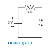
Chapter 28, Problem 3CQ
The wire is broken on the right side of the circuit in FIGURE Q28.3. What is the potential difference
Expert Solution & Answer
Want to see the full answer?
Check out a sample textbook solution
Students have asked these similar questions
Please solve and answer the problem correctly please. Be sure to give explanations on each step and write neatlyplease. Thank you!! ( preferably type the explantion, steps and solution please )
A square coil that has 17.5 cm on each side containing 17 loops lies
flat on your desk as shown on this page. A uniform magnetic field
of magnitude 4.60 × 10-ST points into this page. If a 8.50-A clockwise
Current flows through the coil.
ca) determine the torque on the coil.
N.m
(b) which edge of the coil rises up? choose one
。 Bottom
отор
and explain.
O
Right
• None of these
О
Left.
A circular loop of wire with a diameter of 13.0 cm is in the horizontal
plane and carries of 1.70 A clockwise, as viewed from underneath.
What is the magnitude magnetic field as the center of the loop?
-T what is the direction of magnetic field at the center
or down?
please explain.
of the loop?
up
Chapter 28 Solutions
Physics for Scientists and Engineers: A Strategic Approach with Modern Physics (4th Edition)
Ch. 28 - Rank in order, from largest to smallest, the...Ch. 28 - The tip of a flashlight bulb is touching the top...Ch. 28 - The wire is broken on the right side of the...Ch. 28 - The circuit of FIGURE Q28.4 has two resistors,...Ch. 28 - The circuit of FIGURE Q28.5 has two resistors,...Ch. 28 - Rank in order, from largest to smallest, the...Ch. 28 - Are the two resistors in FIGURE Q28.7 in series or...Ch. 28 - A battery with internal resistance r is connected...Ch. 28 - Initially bulbs A and B in FIGURE Q28.9 are...Ch. 28 - Bulbs A. B, and C in FIGURE Q28.1O axe identical,...
Ch. 28 - Bulbs A and B in FIGURE Q28.11 are identical, and...Ch. 28 - Prob. 12CQCh. 28 - FIGURE Q28.13 shows the voltage as a function of...Ch. 28 - Prob. 1EAPCh. 28 - Draw a circuit diagram for the circuit of FIGURE...Ch. 28 - Prob. 3EAPCh. 28 - Prob. 4EAPCh. 28 - a. What are the magnitude and direction of the...Ch. 28 - What is the magnitude of the potential difference...Ch. 28 - Prob. 7EAPCh. 28 - Prob. 8EAPCh. 28 - A 60 W lightbulb and a 100 W lightbulb are placed...Ch. 28 - Prob. 10EAPCh. 28 - The five identical bulbs in FIGURE EX2B.11 are all...Ch. 28 - Prob. 12EAPCh. 28 - Prob. 13EAPCh. 28 - A typical American family uses kWh of electricity...Ch. 28 - A waterbed heater uses 450 W of power. It is on 25...Ch. 28 - Prob. 16EAPCh. 28 - Prob. 17EAPCh. 28 - Prob. 18EAPCh. 28 - 19. The voltage across the terminals of a V...Ch. 28 - Prob. 20EAPCh. 28 - Prob. 21EAPCh. 28 - 22. Two of the three resistors in FIGURE EX28.22...Ch. 28 - What is the value of resistor R in FIGURE EX28.23?Ch. 28 - Prob. 24EAPCh. 28 - What is the equivalent resistance between points a...Ch. 28 - What is the equivalent resistance between points a...Ch. 28 - Prob. 27EAPCh. 28 - Prob. 28EAPCh. 28 - Prob. 29EAPCh. 28 - Prob. 30EAPCh. 28 - Prob. 31EAPCh. 28 - Prob. 32EAPCh. 28 - Prob. 33EAPCh. 28 - What is the time constant for the discharge of the...Ch. 28 - A 10F capacitor initially charged to 20C is...Ch. 28 - Prob. 36EAPCh. 28 - Prob. 37EAPCh. 28 - A capacitor is discharged through a resistor. The...Ch. 28 - Prob. 39EAPCh. 28 - 40. A refrigerator has a 1000 W compressor, but...Ch. 28 - Prob. 41EAPCh. 28 - An electric eel develops a potential difference...Ch. 28 - You have a resistor, a resistor, a resistor, and a...Ch. 28 - A 2.0 -m-long, 1.0 -mm-diameter wire has a...Ch. 28 - What is the equivalent resistance between points a...Ch. 28 - What are the emf and internal resistance of the...Ch. 28 - A string of holiday lights can be wired in series,...Ch. 28 - The circuit shown in FIGURE P28.48 is inside a 15...Ch. 28 - Suppose you have resistors 2.5,3.5, and 4.5 and a...Ch. 28 - A lightbulb is in series with a resistor. The...Ch. 28 - Prob. 51EAPCh. 28 - Prob. 52EAPCh. 28 - Prob. 53EAPCh. 28 - Prob. 54EAPCh. 28 - What are the battery current Ibatand the potential...Ch. 28 - A battery is a voltage source, always providing...Ch. 28 - A circuit you’re building needs an ammeter that...Ch. 28 - For the circuit shown in FIGURE P28.58, find the...Ch. 28 - For the circuit shown in FIGURE P28.59, find the...Ch. 28 - For the circuit shown in FIGURE P28.60, find the...Ch. 28 - What is the current through the 20 resistor in...Ch. 28 - For the circuit shown in FIGURE P28.62, find the...Ch. 28 - What is the current through the 10 resistor in...Ch. 28 - For what emf does the 200 resistor in FIGURE...Ch. 28 - Prob. 65EAPCh. 28 - Prob. 66EAPCh. 28 - Prob. 67EAPCh. 28 - II A circuit you're using discharges a 20F...Ch. 28 - A 150F defibrillator capacitor is charged to 1500V...Ch. 28 - Prob. 70EAPCh. 28 - A 0.25F capacitor is charged to 50 V. It is then...Ch. 28 - Prob. 72EAPCh. 28 - Prob. 73EAPCh. 28 - The capacitors in FIGURE P28.74 are charged and...Ch. 28 - Prob. 75EAPCh. 28 - Prob. 76EAPCh. 28 - Prob. 77EAPCh. 28 - Prob. 78EAPCh. 28 - Prob. 79EAPCh. 28 - Prob. 80EAPCh. 28 - Prob. 81EAPCh. 28 - Prob. 82EAP
Knowledge Booster


Learn more about
Need a deep-dive on the concept behind this application? Look no further. Learn more about this topic, physics and related others by exploring similar questions and additional content below.Similar questions
- Starlord has a mass of 89.3 kg and Groot is pulling the bag with a force of 384. N at an angle of 35.0˚ as is shown in the figure below. What is the coefficient of kinetic friction if they are moving at a constant speed of 2.31 m/s?arrow_forwardEarly on in the video game Shadow of the Tomb Raider Lara Croft uses a winch to pull a heavy crate of stone up a 23.6° incline. If Lara causes the 66.0 kg crate to accelerate at 2.79 m/s2 up the ramp, what is the tension in the rope pulling the block? The coefficient of kinetic friction between the block and the ground is 0.503.arrow_forwardA player kicks a football at the start of the game. After a 4 second flight, the ball touches the ground 50 m from the kicking tee. Assume air resistance is negligible and the take-off and landing height are the same (i.e., time to peak = time to fall = ½ total flight time). (Note: For each question draw a diagram to show the vector/s. Show all the step and provide units in the answers. Provide answer to 2 decimal places unless stated otherwise.) Calculate and answer all parts. Only use equations PROVIDED:arrow_forward
- A shot putter releases a shot at 13 m/s at an angle of 42 degrees to the horizontal and from a height of 1.83 m above the ground. (Note: For each question draw a diagram to show the vector/s. Show all the step and provide units in the answers. Provide answer to 2 decimal places unless stated otherwise.) Calculate and answer all parts. Only use equations PROVIDED:arrow_forwardIf a person jumps upwards with a vertical velocity of 5 m/s, What is their velocity 0.5 second into the jump?arrow_forwardA solid sphere 22 cm in radius carries 17 μC, distributed uniformly throughout its volume. Part A Find the electric field strength 12 cm from the sphere's center. Express your answer using two significant figures. E₁ = ΜΕ ΑΣΦ ха Хь b Submit Previous Answers Request Answer <☑ × Incorrect; Try Again; 4 attempts remaining ▾ Part B ? |X| X.10" <☑ Find the electric field strength 22 cm from the sphere's center. Express your answer using two significant figures. ΜΕ ΑΣΦ E2 = Submit Request Answer ▾ Part C ? MN/C Find the electric field strength 44 cm from the sphere's center. Express your answer using two significant figures. ΕΠΙ ΑΣΦ E3 = Submit Request Answer ? MN/C MN/Carrow_forward
- No chatgpt plsarrow_forwardIn a naval battle, a battleship is attempting to fire on a destroyer. The battleship is a distance d1 = 2,150 m to the east of the peak of a mountain on an island, as shown in the figure below. The destroyer is attempting to evade cannon shells fired from the battleship by hiding on the west side of the island. The initial speed of the shells that the battleship fires is vi = 245 m/s. The peak of the mountain is h = 1,840 m above sea level, and the western shore of the island is a horizontal distance d2 = 250 m from the peak. What are the distances (in m), as measured from the western shore of the island, at which the destroyer will be safe from fire from the battleship? (Note the figure is not to scale. You may assume that the height and width of the destroyer are small compared to d1 and h.)arrow_forwardNo chatgpt plsarrow_forward
- The law of reflection applies to Question 14Select one: a. specular reflection b. irregular reflection c. All of these d. diffuse reflectionarrow_forwardAccording to your book "normal" human body temperature is considered to be ________? Select one: a. none of these b. 98.6°C c. 37°C d. 100°Carrow_forwardProblem Seven. A football receiver running straight downfield at 5.60 m/s is 11.5 m in front of the quarterback when a pass is thrown downfield at an angle of 35.0° above the horizon. 8.) If the receiver never changes speed and the ball is caught at the same height from which it was thrown, find the distance between the quarterback and the receiver when the catch is made. (A) 21.3 (B) 17.8 (C) 18.8 (D) 19.9 (E) 67.5arrow_forward
arrow_back_ios
SEE MORE QUESTIONS
arrow_forward_ios
Recommended textbooks for you
 Physics for Scientists and EngineersPhysicsISBN:9781337553278Author:Raymond A. Serway, John W. JewettPublisher:Cengage Learning
 Physics for Scientists and Engineers with Modern ...PhysicsISBN:9781337553292Author:Raymond A. Serway, John W. JewettPublisher:Cengage Learning
 Physics for Scientists and Engineers: Foundations...PhysicsISBN:9781133939146Author:Katz, Debora M.Publisher:Cengage Learning
 Principles of Physics: A Calculus-Based TextPhysicsISBN:9781133104261Author:Raymond A. Serway, John W. JewettPublisher:Cengage Learning
 Physics for Scientists and Engineers, Technology ...PhysicsISBN:9781305116399Author:Raymond A. Serway, John W. JewettPublisher:Cengage Learning
Physics for Scientists and Engineers
Physics
ISBN:9781337553278
Author:Raymond A. Serway, John W. Jewett
Publisher:Cengage Learning
Physics for Scientists and Engineers with Modern ...
Physics
ISBN:9781337553292
Author:Raymond A. Serway, John W. Jewett
Publisher:Cengage Learning
Physics for Scientists and Engineers: Foundations...
Physics
ISBN:9781133939146
Author:Katz, Debora M.
Publisher:Cengage Learning
Principles of Physics: A Calculus-Based Text
Physics
ISBN:9781133104261
Author:Raymond A. Serway, John W. Jewett
Publisher:Cengage Learning
Physics for Scientists and Engineers, Technology ...
Physics
ISBN:9781305116399
Author:Raymond A. Serway, John W. Jewett
Publisher:Cengage Learning
DC Series circuits explained - The basics working principle; Author: The Engineering Mindset;https://www.youtube.com/watch?v=VV6tZ3Aqfuc;License: Standard YouTube License, CC-BY