Physics for Scientists and Engineers: A Strategic Approach with Modern Physics (4th Edition)
4th Edition
ISBN: 9780133942651
Author: Randall D. Knight (Professor Emeritus)
Publisher: PEARSON
expand_more
expand_more
format_list_bulleted
Videos
Textbook Question
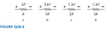
Chapter 28, Problem 6CQ
Rank in order, from largest to smallest, the powers
Expert Solution & Answer
Want to see the full answer?
Check out a sample textbook solution
Students have asked these similar questions
The law of reflection applies to
Question 14Select one:
a.
specular reflection
b.
irregular reflection
c.
All of these
d.
diffuse reflection
According to your book "normal" human body temperature is considered to be ________?
Select one:
a. none of these
b.
98.6°C
c.
37°C
d.
100°C
Problem Seven. A football
receiver
running
straight
downfield at 5.60 m/s is 11.5 m
in front of the quarterback when
a pass is thrown downfield at an
angle of 35.0° above the
horizon.
8.) If the receiver never changes speed and the ball is caught at the same height from which it was
thrown, find the distance between the quarterback and the receiver when the catch is made.
(A) 21.3
(B) 17.8
(C) 18.8
(D) 19.9
(E) 67.5
Chapter 28 Solutions
Physics for Scientists and Engineers: A Strategic Approach with Modern Physics (4th Edition)
Ch. 28 - Rank in order, from largest to smallest, the...Ch. 28 - The tip of a flashlight bulb is touching the top...Ch. 28 - The wire is broken on the right side of the...Ch. 28 - The circuit of FIGURE Q28.4 has two resistors,...Ch. 28 - The circuit of FIGURE Q28.5 has two resistors,...Ch. 28 - Rank in order, from largest to smallest, the...Ch. 28 - Are the two resistors in FIGURE Q28.7 in series or...Ch. 28 - A battery with internal resistance r is connected...Ch. 28 - Initially bulbs A and B in FIGURE Q28.9 are...Ch. 28 - Bulbs A. B, and C in FIGURE Q28.1O axe identical,...
Ch. 28 - Bulbs A and B in FIGURE Q28.11 are identical, and...Ch. 28 - Prob. 12CQCh. 28 - FIGURE Q28.13 shows the voltage as a function of...Ch. 28 - Prob. 1EAPCh. 28 - Draw a circuit diagram for the circuit of FIGURE...Ch. 28 - Prob. 3EAPCh. 28 - Prob. 4EAPCh. 28 - a. What are the magnitude and direction of the...Ch. 28 - What is the magnitude of the potential difference...Ch. 28 - Prob. 7EAPCh. 28 - Prob. 8EAPCh. 28 - A 60 W lightbulb and a 100 W lightbulb are placed...Ch. 28 - Prob. 10EAPCh. 28 - The five identical bulbs in FIGURE EX2B.11 are all...Ch. 28 - Prob. 12EAPCh. 28 - Prob. 13EAPCh. 28 - A typical American family uses kWh of electricity...Ch. 28 - A waterbed heater uses 450 W of power. It is on 25...Ch. 28 - Prob. 16EAPCh. 28 - Prob. 17EAPCh. 28 - Prob. 18EAPCh. 28 - 19. The voltage across the terminals of a V...Ch. 28 - Prob. 20EAPCh. 28 - Prob. 21EAPCh. 28 - 22. Two of the three resistors in FIGURE EX28.22...Ch. 28 - What is the value of resistor R in FIGURE EX28.23?Ch. 28 - Prob. 24EAPCh. 28 - What is the equivalent resistance between points a...Ch. 28 - What is the equivalent resistance between points a...Ch. 28 - Prob. 27EAPCh. 28 - Prob. 28EAPCh. 28 - Prob. 29EAPCh. 28 - Prob. 30EAPCh. 28 - Prob. 31EAPCh. 28 - Prob. 32EAPCh. 28 - Prob. 33EAPCh. 28 - What is the time constant for the discharge of the...Ch. 28 - A 10F capacitor initially charged to 20C is...Ch. 28 - Prob. 36EAPCh. 28 - Prob. 37EAPCh. 28 - A capacitor is discharged through a resistor. The...Ch. 28 - Prob. 39EAPCh. 28 - 40. A refrigerator has a 1000 W compressor, but...Ch. 28 - Prob. 41EAPCh. 28 - An electric eel develops a potential difference...Ch. 28 - You have a resistor, a resistor, a resistor, and a...Ch. 28 - A 2.0 -m-long, 1.0 -mm-diameter wire has a...Ch. 28 - What is the equivalent resistance between points a...Ch. 28 - What are the emf and internal resistance of the...Ch. 28 - A string of holiday lights can be wired in series,...Ch. 28 - The circuit shown in FIGURE P28.48 is inside a 15...Ch. 28 - Suppose you have resistors 2.5,3.5, and 4.5 and a...Ch. 28 - A lightbulb is in series with a resistor. The...Ch. 28 - Prob. 51EAPCh. 28 - Prob. 52EAPCh. 28 - Prob. 53EAPCh. 28 - Prob. 54EAPCh. 28 - What are the battery current Ibatand the potential...Ch. 28 - A battery is a voltage source, always providing...Ch. 28 - A circuit you’re building needs an ammeter that...Ch. 28 - For the circuit shown in FIGURE P28.58, find the...Ch. 28 - For the circuit shown in FIGURE P28.59, find the...Ch. 28 - For the circuit shown in FIGURE P28.60, find the...Ch. 28 - What is the current through the 20 resistor in...Ch. 28 - For the circuit shown in FIGURE P28.62, find the...Ch. 28 - What is the current through the 10 resistor in...Ch. 28 - For what emf does the 200 resistor in FIGURE...Ch. 28 - Prob. 65EAPCh. 28 - Prob. 66EAPCh. 28 - Prob. 67EAPCh. 28 - II A circuit you're using discharges a 20F...Ch. 28 - A 150F defibrillator capacitor is charged to 1500V...Ch. 28 - Prob. 70EAPCh. 28 - A 0.25F capacitor is charged to 50 V. It is then...Ch. 28 - Prob. 72EAPCh. 28 - Prob. 73EAPCh. 28 - The capacitors in FIGURE P28.74 are charged and...Ch. 28 - Prob. 75EAPCh. 28 - Prob. 76EAPCh. 28 - Prob. 77EAPCh. 28 - Prob. 78EAPCh. 28 - Prob. 79EAPCh. 28 - Prob. 80EAPCh. 28 - Prob. 81EAPCh. 28 - Prob. 82EAP
Knowledge Booster


Learn more about
Need a deep-dive on the concept behind this application? Look no further. Learn more about this topic, physics and related others by exploring similar questions and additional content below.Similar questions
- When two bar magnets are near each other, the north pole of one of the magnets experiences what type of force from the other magnet? 1. both an attractive force and a repulsive force 2. a Coulomb force 3. only an attractive force 4. only a repulsive forcearrow_forwardWhat can be said about the electric force between two charged particles? It varies as 1/r. It depends only on the magnitudes of the charges. It is much, much greater than the attractive gravitational force. It is repulsive for unlike charges.arrow_forwardA piece of copper originally 305mm long is pulled in tension with a stress of 276MPa. If the deformation is elastic, what will be the resultant elongation. E for copper is 110Gpaarrow_forward
- Please solve and answer the problem correctly please. Be sure to give explanations on each step and write neatly please. Thank you!!arrow_forwardIn the figures, the masses are hung from an elevator ceiling. Assume the velocity of the elevator is constant. Find the tensions in the ropes (in N) for each case. Note that 0₁ = 35.0°, 0₂ = 55.0°, 03 = 60.0°, m₁ = 3.00 kg, and m2 = 7.00 kg. (Due to the nature of this problem, do not use rounded intermediate values-including answers submitted in WebAssign-in your calculations.) (a) Τι WY NY MY T3 e₁ T₁ = N = N = N (b) 18 Τι = Τι T3 = || || || = T T Ts m₂ N N N 02 T₂ T3 m₁arrow_forwardYou are working with a movie director and investigating a scene with a cowboy sliding off a tree limb and falling onto the saddle of a moving horse. The distance of the fall is several meters, and the calculation shows a high probability of injury to the cowboy from the stunt. Let's look at a simpler situation. Suppose the director asks you to have the cowboy step off a platform 2.55 m off the ground and land on his feet on the ground. The cowboy keeps his legs straight as he falls, but then bends at the knees as soon as he touches the ground. This allows the center of mass of his body to move through a distance of 0.660 m before his body comes to rest. (Center of mass will be formally defined in Linear Momentum and Collisions.) You assume this motion to be under constant acceleration of the center of mass of his body. To assess the degree of danger to the cowboy in this stunt, you wish to calculate the average force upward on his body from the ground, as a multiple of the cowboy's…arrow_forward
- A box of mass m = 2.00 kg is released from rest at the top of an inclined plane as seen in the figure. The box starts out at height h =0.200 m above the top of the table, the table height is H = 2.00 m, and 0 = 41.0°. H m (a) What is the acceleration (in m/s²) of the box while it slides down the incline? m/s² (b) What is the speed (in m/s) of the box when it leaves the incline? m/s (c) At what horizontal distance (in m) from the end of the table will the box hit the ground? m (d) How long (in s) from when the box is released does it hit the ground? S (e) Does the box's mass affect any of your above answers? Yes Noarrow_forward(a) A sphere made of rubber has a density of 0.940 g/cm³ and a radius of 7.00 cm. It falls through air of density 1.20 kg/m³ and has a drag coefficient of 0.500. What is its terminal speed (in m/s)? m/s (b) From what height (in m) would the sphere have to be dropped to reach this speed if it fell without air resistance? marrow_forwardThe systems shown below are in equilibrium. If the spring scales are calibrated in newtons, what do they read? Ignore the masses of the pulleys and strings and assume the pulleys and the incline are frictionless. (Let m = 2.19 kg and € = 29.0°.) scale in (a) N N scale in (b) scale in (c) N scale in (d) N a C m m m m m b d m Ꮎarrow_forward
- An elevator car has two equal masses attached to the ceiling as shown. (Assume m = 3.10 kg.) m m T₁ T2 (a) The elevator ascends with an acceleration of magnitude 2.00 m/s². What are the tensions in the two strings? (Enter your answers in N.) = N T₁ Τι = N (b) The maximum tension the strings can withstand is 78.8 N. What is the maximum acceleration of the elevator so that a string does not break? (Enter the magnitude in m/s².) m/s²arrow_forward(a) At what speed (in m/s) will a proton move in a circular path of the same radius as an electron that travels at 7.85 x 100 m/s perpendicular to the Earth's magnetic field at an altitude where the field strength is 1.20 x 10⁻⁵ T? 4.27e3 m/s (b) What would the radius (in m) of the path be if the proton had the same speed as the electron? 7.85e6 x m (c) What would the radius (in m) be if the proton had the same kinetic energy as the electron? 195.38 x m (d) What would the radius (in m) be if the proton had the same momentum as the electron? 3.7205 marrow_forward! Required information The block shown is made of a magnesium alloy, for which E = 45 GPa and v = 0.35. Know that σx = -185 MPa. NOTE: This is a multi-part question. Once an answer is submitted, you will be unable to return to this part. 25 mm B D 40 mm 100 mm Determine the magnitude of Oy for which the change in the height of the block will be zero. The magnitude of Oy is MPa.arrow_forward
arrow_back_ios
SEE MORE QUESTIONS
arrow_forward_ios
Recommended textbooks for you
 Physics for Scientists and Engineers: Foundations...PhysicsISBN:9781133939146Author:Katz, Debora M.Publisher:Cengage Learning
 Principles of Physics: A Calculus-Based TextPhysicsISBN:9781133104261Author:Raymond A. Serway, John W. JewettPublisher:Cengage Learning
 Physics for Scientists and EngineersPhysicsISBN:9781337553278Author:Raymond A. Serway, John W. JewettPublisher:Cengage Learning
 Physics for Scientists and Engineers with Modern ...PhysicsISBN:9781337553292Author:Raymond A. Serway, John W. JewettPublisher:Cengage Learning
 Physics for Scientists and Engineers, Technology ...PhysicsISBN:9781305116399Author:Raymond A. Serway, John W. JewettPublisher:Cengage Learning
Physics for Scientists and Engineers: Foundations...
Physics
ISBN:9781133939146
Author:Katz, Debora M.
Publisher:Cengage Learning
Principles of Physics: A Calculus-Based Text
Physics
ISBN:9781133104261
Author:Raymond A. Serway, John W. Jewett
Publisher:Cengage Learning
Physics for Scientists and Engineers
Physics
ISBN:9781337553278
Author:Raymond A. Serway, John W. Jewett
Publisher:Cengage Learning
Physics for Scientists and Engineers with Modern ...
Physics
ISBN:9781337553292
Author:Raymond A. Serway, John W. Jewett
Publisher:Cengage Learning
Physics for Scientists and Engineers, Technology ...
Physics
ISBN:9781305116399
Author:Raymond A. Serway, John W. Jewett
Publisher:Cengage Learning
DC Series circuits explained - The basics working principle; Author: The Engineering Mindset;https://www.youtube.com/watch?v=VV6tZ3Aqfuc;License: Standard YouTube License, CC-BY