
University Physics (14th Edition)
14th Edition
ISBN: 9780133969290
Author: Hugh D. Young, Roger A. Freedman
Publisher: PEARSON
expand_more
expand_more
format_list_bulleted
Videos
Textbook Question
Chapter 26, Problem 26.64P
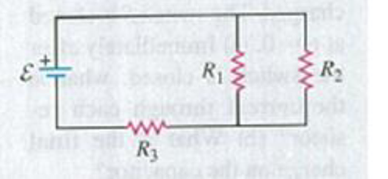
In the circuit shown in Fig. P26.64, ε = 24.0 V, R1, = 6.00 Ω, R3 = 12.0 Ω, and R2 can vary between 3.00 Ω and 24.0 Ω. For what value of R2 is the power dissipated by heating element R1 the greatest? Calculate the magnitude of the greatest power.
Figure P26.64
Expert Solution & Answer
Want to see the full answer?
Check out a sample textbook solution
Students have asked these similar questions
The figure shows a simple RC circuit consisting of a 100.0-V battery in series with a 10.0-µF capacitor and a resistor. Initially, the
switch S is open and the capacitor is uncharged. Two seconds after the switch is closed, the voltage across the resistor is 37 V.
R
S
www
100.0 V
T
3
0.0.37 Ω
O 2.0 × 10⁵Q
Ο 2.70 Ω
O 4.3 × 10⁵Q
O 5.0 × 10⁴Q
10.0 uF
Determine the numerical value of the resistance R.
Six resistors R1=6.00 Ω, R2=2.00 Ω, R3=11.0 Ω, R4=10.0 Ω, R5=10.0 Ω, and R6=7.00 Ω are mounted as shown in the figure. The voltage of the battery is V = 14 Volts. What is the power dissipated in the R5 resistor?
A series circuit is comprised of a 200VDC battery, a switch, a 1 MΩ resistor and a 10 µF capacitor.
Initially the switch is open and the capacitor is uncharged.
What is the capacitor voltage 26 seconds after the switch is closed?
Your answer should be in V.
Chapter 26 Solutions
University Physics (14th Edition)
Ch. 26 - In which 120-V light bulb does the filament have...Ch. 26 - Two 120-V light bulbs, one 25-W and one 200-W,...Ch. 26 - You connect a number of identical light bulbs to a...Ch. 26 - In the circuit shown in Fig. Q26.4, three...Ch. 26 - If two resistors R1 and R2 (R2 R1) are connected...Ch. 26 - If two resistors R1 and R2 (R2 R1) are connected...Ch. 26 - A battery with no internal resistance is connected...Ch. 26 - A resistor consists of three identical metal...Ch. 26 - A light bulb is connected in the circuit shown in...Ch. 26 - A real battery, having nonnegligible internal...
Ch. 26 - If the battery in Discussion Question Q26.10 is...Ch. 26 - Consider the circuit shown in Fig. Q26.12. What...Ch. 26 - Is it possible to connect resistors together in a...Ch. 26 - The battery in the circuit shown in Fig. Q26.14...Ch. 26 - In a two-cell flashlight, the batteries are...Ch. 26 - Identical light bulbs A, B, and C are connected as...Ch. 26 - The emf of a flashlight battery is roughly...Ch. 26 - Will the capacitors in the circuits shown in Fig....Ch. 26 - Verify that the time constant RC has units of...Ch. 26 - For very large resistances it is easy to construct...Ch. 26 - When a capacitor, battery, and resistor are...Ch. 26 - A uniform wire of resistance R is cut into three...Ch. 26 - A machine part has a resistor X protruding from an...Ch. 26 - A resistor with R1 = 25.0 is connected to a...Ch. 26 - A 42- resistor and a 20- resistor are connected in...Ch. 26 - A triangular array of resistors is shown in Fig....Ch. 26 - For the circuit shown in Fig. E26.6 both meters...Ch. 26 - For the circuit shown in Fig. E26.7 find the...Ch. 26 - Three resistors having resistances of 1.60 , 2.40...Ch. 26 - Now the three resistors of Exercise 26.8 are...Ch. 26 - Power Rating of a Resistor. The power rating of a...Ch. 26 - In Fig. E26.11, R1, = 3.00 , R2 = 6.00 , and R3=...Ch. 26 - In Fig. E26.11 the battery has emf 35.0 V and...Ch. 26 - Compute the equivalent resistance of the network...Ch. 26 - Compute the equivalent resistance of the network...Ch. 26 - In the circuit of Fig. E26.15, each resistor...Ch. 26 - Consider the circuit shown in Fig. E26.16. The...Ch. 26 - In the circuit shown in Fig. E26.17, the voltage...Ch. 26 - In the circuit shown in Fig. E26.18, = 36.0 V,...Ch. 26 - CP In the circuit in Fig. E26.19, a 20.0- resistor...Ch. 26 - In the circuit shown in Fig. E26.20, the rate at...Ch. 26 - Light Bulbs in Series and in Parallel. Two light...Ch. 26 - Light Bulbs in Series. A 60-W, 120-V light bulb...Ch. 26 - In the circuit shown in Fig. E26.23, ammeter A1...Ch. 26 - The batteries shown in the circuit in Fig. E26.24...Ch. 26 - In the circuit shown in Fig. E26.25 find (a) the...Ch. 26 - Find the emfs 1 and 2 in the circuit of Fig....Ch. 26 - In the circuit shown in Fig. E26.27, find (a) the...Ch. 26 - In the circuit shown in Fig. E26.28, find (a) the...Ch. 26 - The 10.00-V battery in Fig. E26.28 is removed from...Ch. 26 - The 5.00-V battery in Fig. E26.28 is removed from...Ch. 26 - In the circuit shown in Fig. E26.31 the batteries...Ch. 26 - In the circuit shown in Fig. E26.32 both batteries...Ch. 26 - In the circuit shown in Fig. E26.33 all meters are...Ch. 26 - In the circuit shown in Fig. E26.34, the 6.0-...Ch. 26 - The resistance of a galvanometer coil is 25.0 ,...Ch. 26 - The resistance of the coil of a pivoted coil...Ch. 26 - A circuit consists of a series combination of...Ch. 26 - A galvanometer having a resistance of 25.0 has a...Ch. 26 - A capacitor is charged to a potential of 12.0 V...Ch. 26 - You connect a battery, resistor, and capacitor as...Ch. 26 - A 4.60-F capacitor that is initially uncharged is...Ch. 26 - You connect a battery, resistor, and capacitor as...Ch. 26 - CP In the circuit shown in Fig. E26.43 both...Ch. 26 - A 12.4-F capacitor is connected through a 0.895-M...Ch. 26 - An emf source with = 120 V, a resistor with R =...Ch. 26 - A resistor and a capacitor are connected in series...Ch. 26 - CP In the circuit shown in Fig. E26.47 each...Ch. 26 - A 1.50-F capacitor is charging through a 12.0-...Ch. 26 - In the circuit in Fig. E26.49 the capacitors are...Ch. 26 - A 12.0-F capacitor is charged to a potential of...Ch. 26 - In the circuit shown in Fig. E26.51, C = 5.90 F, ...Ch. 26 - Prob. 26.52ECh. 26 - A 1500-W electric beater is plugged into the...Ch. 26 - In Fig. P26.54, the battery has negligible...Ch. 26 - The two identical light bulbs in Example 26.2...Ch. 26 - Each of the three resistors in Fig. P26.56 has a...Ch. 26 - (a) Find the potential of point a with respect to...Ch. 26 - CP For the circuit shown in Fig. P26.58 a 20.0-...Ch. 26 - Calculate the three currents I1, I2, and I3...Ch. 26 - What must the emf in Fig. P26.60 be in order for...Ch. 26 - Find the current through each of the three...Ch. 26 - (a) Find the current through the battery and each...Ch. 26 - Consider the circuit shown in Fig. P26.63. (a)...Ch. 26 - In the circuit shown in Fig. P26.64, = 24.0 V,...Ch. 26 - In the circuit shown in Fig. P26.65, the current...Ch. 26 - In the circuit shown in Fig. P26.66 all the...Ch. 26 - Figure P26.67 employs a convention often used in...Ch. 26 - Three identical resistors are connected in series....Ch. 26 - A resistor R1 consumes electrical power P1 when...Ch. 26 - The capacitor in Fig. F26.70 is initially...Ch. 26 - A 2.00-F capacitor that is initially uncharged is...Ch. 26 - A 6.00-F capacitor that is initially uncharged is...Ch. 26 - Point a in Fig. P26.73 is maintained at a constant...Ch. 26 - The Wheatstone Bridge. The circuit shown in Fig....Ch. 26 - (See Problem 26.67.) (a) What is the potential of...Ch. 26 - A 2.36-F capacitor that is initially uncharged is...Ch. 26 - A 224- resistor and a 589- resistor are connected...Ch. 26 - A resistor with R = 850 is connected to the...Ch. 26 - A capacitor that is initially uncharged is...Ch. 26 - DATA You set up the circuit shown in Fig. 26.22a,...Ch. 26 - DATA You set up the circuit shown in Fig. 26.20....Ch. 26 - DATA The electronics supply company where you work...Ch. 26 - An Infinite Network. As shown in Fig. P26.83, a...Ch. 26 - Suppose a resistor R lies along each edge of a...Ch. 26 - BIO Attenuator Chains and Axons. The infinite...Ch. 26 - Assume that a typical open ion channel spanning an...Ch. 26 - In a simple model of an axon conducting a nerve...Ch. 26 - Cell membranes across a wide variety of organisms...
Additional Science Textbook Solutions
Find more solutions based on key concepts
3. What is free-fall, and why does it make you weightless? Briefly describe why astronauts are weightless in th...
The Cosmic Perspective (8th Edition)
Name two properties of minerals that are based on the minerals crystal structure.
Conceptual Integrated Science
A physicist lost in the mountains tries to make a telescope using the lenses from his reading glasses. They hav...
Physics for Scientists and Engineers with Modern Physics
Using the definitions in Eqs. 1.1 and 1.4, and appropriate diagrams, show that the dot product and cross produc...
Introduction to Electrodynamics
Knowledge Booster


Learn more about
Need a deep-dive on the concept behind this application? Look no further. Learn more about this topic, physics and related others by exploring similar questions and additional content below.Similar questions
- The values of the components in a simple series RC circuit containing a switch (Fig. P21.53) are C = 1.00 F, R = 2.00 106 , and = 10.0 V. At the instant 10.0 s after the switch is closed, calculate (a) the charge on the capacitor, (b) the current in the resistor, (c) the rate at which energy is being stored in the capacitor, and (d) the rate at which energy is being delivered by the battery.arrow_forwardConsider a series RC circuit as in Figure P18.35 for which R = 1.00 M, C = 5.00 F, and = 30.0 V. Find (a) the time constant of the circuit and (b) the maximum charge on the capacitor after the switch is thrown closed. (c) Find the current in the resistor 10.0 s after the switch is closed. Figure P18.35 Problem 35 and 38.arrow_forwardIf the terminals of a battery with zero internal resistance are connected across two identical resistors in series, the total power delivered by the battery is 8.00 W. If the same battery is connected across the same resistors in parallel, what is the total power delivered by the battery? (a) 16.0 W (b) 32.0 W (c) 2.00 W (d) 4.00 W (e) none of those answersarrow_forward
- The circuit shown in Figure P28.78 is set up in the laboratory to measure an unknown capacitance C in series with a resistance R = 10.0 M powered by a battery whose emf is 6.19 V. The data given in the table are the measured voltages across the capacitor as a function of lime, where t = 0 represents the instant at which the switch is thrown to position b. (a) Construct a graph of In (/v) versus I and perform a linear least-squares fit to the data, (b) From the slope of your graph, obtain a value for the time constant of the circuit and a value for the capacitance. v(V) t(s) In (/v) 6.19 0 5.56 4.87 4.93 11.1 4.34 19.4 3.72 30.8 3.09 46.6 2.47 67.3 1.83 102.2arrow_forwardThree resistors, R1 = 2.55 Ω, R2 = 4.77 Ω, and R3 = 6.55 Ω are connected by ideal metal wires, as shown in the figure. If the voltage dropping through R1 is 4.86 V, what is the power dissipated by R3 (in W)?arrow_forwardThe circuit in the figure below has been connected for a long time. Let R₁ = 8.200 and R₂ = 4.80 0. 1.00 Ω R₁ 10.0 V + Need Help? R₂ (a) What is the potential difference across the capacitor? 6.29 V Read It 1.00μF (b) If the battery is disconnected from the circuit, over what time interval does the capacitor discharge to one-half its initial voltage? μs 2.00 Ω Master Itarrow_forward
- In the figure, three resistors are connected to a voltage source so that R2 and R3 are in parallel with one another and that combination is in series with R1. Calculate I3 using the potential and resistances given in the figure.arrow_forward31. For the circuit shown in Fig- ure P23.31, find the current through and the potential differ- ence across each resistor. Place your results in a table for ease of reading. FIGURE P23.31 6.0 Ω 24 V www 6.0 Ω 15 Ω 4.0 Ω wwarrow_forward24.0 V 4.00 A R 4.00 A Figure N 8. Consider the circuit shown in Figure b. The terminal voltage of the 24.0 V battery is 21.2 V. What is a) the internal resistance r of the battery; b) the resistance R of the circuit resistor???arrow_forward
- A 0.25 μF capacitor is charged to 50 V. It is then connected in series with a 25 Ω resistor and a 100 Ω resistor and allowed to discharge completely. How much energy (3 sf) is dissipated by the 25 Ω resistor?arrow_forwardUsing your data, answer the following questions: a. To three decimal places, what fraction of the total charge does a capacitor in an RC circuit have after charging for 4.15 time constants; the fraction f such that q(4.15t) = fQmaxarrow_forwardA heart pacemaker fires 69 times a minute, each time a 32.0 nF capacitor is charged (by a battery in series with a resistor) to 0.632 of its full voltage. What is the value of the resistance (in Ω)?arrow_forward
arrow_back_ios
SEE MORE QUESTIONS
arrow_forward_ios
Recommended textbooks for you
 College PhysicsPhysicsISBN:9781305952300Author:Raymond A. Serway, Chris VuillePublisher:Cengage Learning
 College PhysicsPhysicsISBN:9781285737027Author:Raymond A. Serway, Chris VuillePublisher:Cengage Learning
 Principles of Physics: A Calculus-Based TextPhysicsISBN:9781133104261Author:Raymond A. Serway, John W. JewettPublisher:Cengage Learning
 Physics for Scientists and Engineers: Foundations...PhysicsISBN:9781133939146Author:Katz, Debora M.Publisher:Cengage Learning
 Physics for Scientists and Engineers, Technology ...PhysicsISBN:9781305116399Author:Raymond A. Serway, John W. JewettPublisher:Cengage Learning
College Physics
Physics
ISBN:9781305952300
Author:Raymond A. Serway, Chris Vuille
Publisher:Cengage Learning
College Physics
Physics
ISBN:9781285737027
Author:Raymond A. Serway, Chris Vuille
Publisher:Cengage Learning
Principles of Physics: A Calculus-Based Text
Physics
ISBN:9781133104261
Author:Raymond A. Serway, John W. Jewett
Publisher:Cengage Learning
Physics for Scientists and Engineers: Foundations...
Physics
ISBN:9781133939146
Author:Katz, Debora M.
Publisher:Cengage Learning
Physics for Scientists and Engineers, Technology ...
Physics
ISBN:9781305116399
Author:Raymond A. Serway, John W. Jewett
Publisher:Cengage Learning
DC Series circuits explained - The basics working principle; Author: The Engineering Mindset;https://www.youtube.com/watch?v=VV6tZ3Aqfuc;License: Standard YouTube License, CC-BY