
Fundamentals of Electric Circuits
6th Edition
ISBN: 9780078028229
Author: Charles K Alexander, Matthew Sadiku
Publisher: McGraw-Hill Education
expand_more
expand_more
format_list_bulleted
Concept explainers
Videos
Textbook Question
thumb_up100%
Chapter 2.4, Problem 5PP
Find v1 and v2 in the circuit of Fig. 2.22.
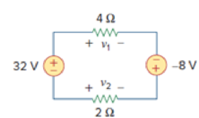
Figure 2.22
For Practice Prob. 2.5.
Expert Solution & Answer
Want to see the full answer?
Check out a sample textbook solution
Students have asked these similar questions
Using the table below, design a third (3th) order Butterworth HPF with a 4 KHz cutoff frequency.
What is the additional stage required to HPF to design a third order BPF. Explain your answe
Order
Stage
poles
DF
2 stage
poles
3 stage
DF
poles
DF
1
1
Optional
2
1.414
3
י
1
1
2
1.848
2
0.765
5
2
1
1.618
1
0.618
6
2
1.932
1.414
2
0.518
.I need the correct answer, and if it's wrong, please fix it
7. The midrange voltage gain of an amplifier is 100. The input RC circuit has a lower critical
frequency of 1 kHz. The actual voltage gain at f-100 Hz is 100.
10. In a high-pass filter, the roll-off region occurs above the critical frequency.
Solve this problem and show all of the work
Chapter 2 Solutions
Fundamentals of Electric Circuits
Ch. 2.2 - The essential component of a toaster is an...Ch. 2.2 - For the circuit shown in Fig. 2.9, calculate the...Ch. 2.2 - A resistor absorbs an instantaneous power of 30...Ch. 2.3 - How many branches and nodes does the circuit in...Ch. 2.4 - Find v1 and v2 in the circuit of Fig. 2.22. Figure...Ch. 2.4 - Find vx and vo in the circuit of Fig. 2.24. Figure...Ch. 2.4 - Find vo and io in the circuit of Fig. 2.26. Figure...Ch. 2.4 - Find the current and voltages in the circuit shown...Ch. 2.6 - By combining the resistors in Fig.2.36, find Req....Ch. 2.6 - Find Rab for the circuit in Fig.2.39. Figure 2.39...
Ch. 2.6 - Calculate Geq in the circuit of Fig.2.41. Figure...Ch. 2.6 - Find v1 and v2 in the circuit shown in Fig. 2.43....Ch. 2.7 - Transform the wye network in Fig. 2.51 to a delta...Ch. 2.7 - For the bridge network in Fig. 2.54, find Rab and...Ch. 2.8 - Refer to Fig. 2.55 and assume there are six light...Ch. 2.8 - Following the ammeter setup of Fig. 2.61. design...Ch. 2 - The reciprocal of resistance is: (a) voltage (b)...Ch. 2 - Prob. 2RQCh. 2 - Prob. 3RQCh. 2 - The maximum current that a 2W, 80 k resistor can...Ch. 2 - Prob. 5RQCh. 2 - The current I in the circuit of Fig. 2.63 is: (a)...Ch. 2 - The current I0 of Fig. 2.64 is: (a) 4 A (b) 2 A...Ch. 2 - In the circuit in Fig. 2.65, V is: (a) 30 V (b) 14...Ch. 2 - Which of the circuit in Fig. 2.66 will give you...Ch. 2 - In the circuit of Fig. 2.67, a decrease in R3...Ch. 2 - Design a problem, complete with a solution, to...Ch. 2 - Find the hot resistance of a light bulb rated 60...Ch. 2 - A bar of silicon is 4 cm long with a circular...Ch. 2 - (a) Calculate current i in Fig. 2.68 when the...Ch. 2 - For the network graph in Fig. 2.69. find the...Ch. 2 - In the network graph shown in Fig. 2.70, determine...Ch. 2 - Determine the number of branches and nodes in the...Ch. 2 - Design a problem, complete with a solution, to...Ch. 2 - Find i1, i2, and i3 in Fig. 2.73. Figure 2.73 For...Ch. 2 - Determine i1 and i2 in the circuit of Fig. 2.74....Ch. 2 - In the circuit of Fig. 2.75, calculate V1 and V2....Ch. 2 - In the circuit in Fig. 2.76, obtain v1, v2, and...Ch. 2 - For the circuit in Fig. 2.77, use KCL to find the...Ch. 2 - Given the circuit in Fig. 2.78, use KVL to find...Ch. 2 - Calculate v and ix in the circuit of Fig. 2.79....Ch. 2 - Determine Vo in the circuit in Fig. 2.80. Figure...Ch. 2 - Obtain v1 through v3 in the circuit of Fig. 2.81....Ch. 2 - Find I and V in the circuit of Fig. 2.82. Figure...Ch. 2 - From the circuit in Fig. 2.83, find I, the power...Ch. 2 - Determine io in the circuit of Fig. 2.84. Figure...Ch. 2 - Find Vx in the circuit of Fig. 2.85. Figure 2.85...Ch. 2 - Find Vo in the circuit in Fig. 2.86 and the power...Ch. 2 - In the circuit shown in Fig. 2.87, determine Vx...Ch. 2 - For the circuit in Fig. 2.88, find Vo/Vs in terms...Ch. 2 - For the network in Fig. 2.89, find the current,...Ch. 2 - For the circuit in Fig. 2.90, io = 3 A. Calculate...Ch. 2 - Calculate Io in the circuit of Fig. 2.91. Figure...Ch. 2 - Design a problem, using Fig. 2.92, to help other...Ch. 2 - All resistors (R) in Fig. 2.93 are 10 each. Find...Ch. 2 - For the circuit in Fig. 2.95, determine i1 to i5....Ch. 2 - Find i1 through i4 in the circuit in Fig. 2.96....Ch. 2 - Obtain v and i in the circuit of Fig. 2.97. Figure...Ch. 2 - Using series/parallel resistance combination, find...Ch. 2 - Calculate Vo and Io in the circuit of Fig. 2.99....Ch. 2 - Find i and Vo in the circuit of Fig. 2.100. Figure...Ch. 2 - Given the circuit in Fig. 2.101 and that the...Ch. 2 - Find Req and io in the circuit of Fig. 2.102....Ch. 2 - Evaluate Req looking into each set of terminals...Ch. 2 - For the ladder network in Fig. 2.104, find I and...Ch. 2 - If Req = 50 in the circuit of Fig. 2.105, find R....Ch. 2 - Reduce each of the circuits in Fig. 2.106 to a...Ch. 2 - Calculate the equivalent resistance Rab at...Ch. 2 - For the circuits in Fig. 2.108, obtain the...Ch. 2 - Find the equivalent resistance at terminals a-b of...Ch. 2 - Find I in the circuit of Fig. 2.110. Figure 2.110Ch. 2 - Find the equivalent resistance Rab in the circuit...Ch. 2 - Convert the circuits in Fig. 2.112 from Y to ....Ch. 2 - Transform the circuits in Fig. 2.113 from to Y....Ch. 2 - Design a problem to help other students better...Ch. 2 - Obtain the equivalent resistance at the terminals...Ch. 2 - For the circuit shown in Fig. 2.116, find the...Ch. 2 - Obtain the equivalent resistance Rab in each of...Ch. 2 - Consider the circuit in Fig. 2.118. Find the...Ch. 2 - Calculate I0 in the circuit of Fig. 2.119. Figure...Ch. 2 - Determine V in the circuit of Fig. 2.120. Figure...Ch. 2 - Find Req and I in the circuit of Fig. 2.121....Ch. 2 - The 150 W tight bulb in Fig. 2.122 is rated at 110...Ch. 2 - If the three bulbs of Prob. 2.59 are connected in...Ch. 2 - As a design engineer, you are asked to design a...Ch. 2 - Prob. 62PCh. 2 - If an ammeter with an internal resistance of 100 ...Ch. 2 - The potentiometer (adjustable resistor) Rx in Fig....Ch. 2 - Design a circuit that uses a dArsonval meter (with...Ch. 2 - A 20-k/V voltmeter reads 10 V full scale. (a) What...Ch. 2 - (a) Obtain the voltage Vo in the circuit of Fig....Ch. 2 - (a) Find the current I in the circuit of Fig....Ch. 2 - A voltmeter used to measure Vo in the circuit in...Ch. 2 - (a) Consider the Wheatstone bridge shown in Fig....Ch. 2 - Figure 2.131 represents a model of a solar...Ch. 2 - Find Vo in the two-way power divider circuit in...Ch. 2 - An ammeter model consists of an ideal ammeter in...Ch. 2 - The circuit in Fig. 2.134 is to control the speed...Ch. 2 - Find Rab in the four-way power divider circuit in...Ch. 2 - Repeat Prob. 2.75 for the eight-way divider shown...Ch. 2 - Suppose your circuit laboratory has the following...Ch. 2 - In the circuit in Fig. 2.137, the wiper divides...Ch. 2 - Prob. 79CPCh. 2 - A loudspeaker is connected to an amplifier as...Ch. 2 - For a specific application, the circuit shown in...Ch. 2 - The pin diagram of a resistance array is shown in...Ch. 2 - Two delicate devices are rated as shown in Fig....
Additional Engineering Textbook Solutions
Find more solutions based on key concepts
How does a computers main memory differ from its auxiliary memory?
Java: An Introduction to Problem Solving and Programming (8th Edition)
17–1C A high-speed aircraft is cruising in still air. How does the temperature of air at the nose of the aircra...
Thermodynamics: An Engineering Approach
How are relationships between tables expressed in a relational database?
Modern Database Management
Assume a telephone signal travels through a cable at two-thirds the speed of light. How long does it take the s...
Electric Circuits. (11th Edition)
Why is the study of database technology important?
Database Concepts (8th Edition)
What types of coolant are used in vehicles?
Automotive Technology: Principles, Diagnosis, And Service (6th Edition) (halderman Automotive Series)
Knowledge Booster


Learn more about
Need a deep-dive on the concept behind this application? Look no further. Learn more about this topic, electrical-engineering and related others by exploring similar questions and additional content below.Similar questions
- Don't use ai to answer I will report you answerarrow_forwardDon't use ai to answer I will report you answerarrow_forwardQ3/A unity-feedback system with the forward transfer function G(S)= K S(S+7) is operating with a closed-loop step response that has 15% overshoot. Do the following: a. Evaluate the steady-state error for a unit ramp input. b. Design a lag compensator to improve the steady-state error by a factor of 20 to get a new dominant closed-loop poles S-3.4+ j5.63. place the pole of the lag compensator at s=-0.01 c. Design a lag compensator using OP amp if R1= 100KS2 R2=10 KS2 and R3= 10Karrow_forward
- Q2: (33 Marks) Design FBD for manufacturing system where a conveyor belt is used to move a cart through a tunnel for processing. The process begins when a worker presses a start push button located at the start of the conveyor. Once the start push button is pressed, the cart moves forward along the conveyor belt and enters the tunnel. When the cart reaches the end of the tunnel, it stops automatically and remains in place for 10-minutes to complete a required operation, such as cooling or drying. After the 10-minute delay, the cart automatically returns to the starting point where the worker is stationed. The system then waits for the worker to press the start push button again, at which point the process is repeated. Start PBO Stop PBO LSI 0 LS 2 Motorarrow_forward1. Find the resolution, current and output voltage for a binary weighted resistor DAC of (applied binary word is (locoj), the resistor values R = 12 kQ, Rf = 6 k2 and VR = 12 V. 2. Convert the following 5-bit digital values (ble 10) to analog, using the R-2R ladder. Assume that the Vs = 10 V, R = Rf = 7 ksarrow_forwardK Q4/ For the unity-feedback system where G(s) = do the following: a. Plot the Nyquist diagram. (S+2)(S+4)(S+6) b. Use your Nyquist diagram to find the range of gain, K, for stabilityarrow_forward
- Q6/ Answer (two) of the following question A For the following G(s), find analytical expressions for the magnitude and phase response and make a plot of the logmagnitude and the phase, using log-frequency in rad/s as the ordinate. G(S)=- 1 (S+2)(S+4)arrow_forwardQ5 Given the system of Figure below, with dominant poles -5.415 t/10.57. design a PID controller so that the system can operate with a peak time that is two-thirds that of the uncompensated system at 20% overshoot to get and with zero steady-state error for a step input and KV= 5.7163sec and final K=4.6. R(s) + E(s) K(s + 8) (s+3)(x+6)(s + 10) C(s)arrow_forward".I need the correct answers with explanations" Answer True or False, then correct errors or explain if any: 1. The term pole in filter terminology refers to the feedback circuit. 2, A voltage shunt feedback with Ai-10, A-20, p 0.45, then Aif will be 1. 3. The integrator Op-Amp circuit can be used to produce square waves. 4. The equivalent circuit of the crystal oscillator is series and parallel (R, C) components. 5. The transistor in a class A power amplifier conducts for the entire input cycle. 6. Bypass capacitors in an amplifier determine the low and high-frequency responses. 7. The midrange voltage gain of an amplifier is 100. The input RC circuit has a lower critical frequency of 1 kHz. The actual voltage gain at f-100 Hz is 100. 8. The Bessel filter types produce almost ripple frequency response. 9. RC phase shift oscillators are based on both positive and negative feedback circuits. 10. In a high-pass filter, the roll-off region occurs above the critical frequency.arrow_forward
- ".I need the correct answers with explanations" Answer True or False and correct errors if found: Marks) 1. The LC oscillator circuits are used to operate in low and moderate frequencies. 2. The voltage series feedback can increase both input and output impedances. 3. A two-pole Sallen-Key high-pass filter contains one capacitor and two resistors. 4. The main feature of a crystal oscillator is the high frequency operation that operates with optoelectronic effect. 5. The max. efficiency of the class B power amplifier is 50%. 6. The Q-point must be centered on the load line for maximum class AB output signal swing. 7. The differentiator Op-Amp can convert the triangle waveform into sinewave. 8. Class AB power amplifier eliminates crossover distortion found in pure class A. 9. RC-phase shift oscillators are based on positive feedback circuits. 10. Bypass capacitors in an amplifier determine the low and high-frequency responses.arrow_forwardK Q2/A For the system G(s)= H(s)=1 9 (s+5)(s+2 )(s+5) a. Draw the Bode log-magnitude and phase plots. b. Find the range of K for stability from your Bode plots. c. Evaluate gain margia, phase margin, zero dB frequency, and 180° frequency from your Bode plots for K = 10,000.arrow_forwardPlease solve this question step by step handwritten solution and do not use ai or chat gpt pleasearrow_forward
arrow_back_ios
SEE MORE QUESTIONS
arrow_forward_ios
Recommended textbooks for you
 Introductory Circuit Analysis (13th Edition)Electrical EngineeringISBN:9780133923605Author:Robert L. BoylestadPublisher:PEARSON
 Delmar's Standard Textbook Of ElectricityElectrical EngineeringISBN:9781337900348Author:Stephen L. HermanPublisher:Cengage Learning
 Programmable Logic ControllersElectrical EngineeringISBN:9780073373843Author:Frank D. PetruzellaPublisher:McGraw-Hill Education
 Fundamentals of Electric CircuitsElectrical EngineeringISBN:9780078028229Author:Charles K Alexander, Matthew SadikuPublisher:McGraw-Hill Education
 Electric Circuits. (11th Edition)Electrical EngineeringISBN:9780134746968Author:James W. Nilsson, Susan RiedelPublisher:PEARSON
 Engineering ElectromagneticsElectrical EngineeringISBN:9780078028151Author:Hayt, William H. (william Hart), Jr, BUCK, John A.Publisher:Mcgraw-hill Education,
Introductory Circuit Analysis (13th Edition)
Electrical Engineering
ISBN:9780133923605
Author:Robert L. Boylestad
Publisher:PEARSON
Delmar's Standard Textbook Of Electricity
Electrical Engineering
ISBN:9781337900348
Author:Stephen L. Herman
Publisher:Cengage Learning
Programmable Logic Controllers
Electrical Engineering
ISBN:9780073373843
Author:Frank D. Petruzella
Publisher:McGraw-Hill Education
Fundamentals of Electric Circuits
Electrical Engineering
ISBN:9780078028229
Author:Charles K Alexander, Matthew Sadiku
Publisher:McGraw-Hill Education
Electric Circuits. (11th Edition)
Electrical Engineering
ISBN:9780134746968
Author:James W. Nilsson, Susan Riedel
Publisher:PEARSON
Engineering Electromagnetics
Electrical Engineering
ISBN:9780078028151
Author:Hayt, William H. (william Hart), Jr, BUCK, John A.
Publisher:Mcgraw-hill Education,
Thevenin's Theorem; Author: Neso Academy;https://www.youtube.com/watch?v=veAFVTIpKyM;License: Standard YouTube License, CC-BY