
Fundamentals of Electric Circuits
6th Edition
ISBN: 9780078028229
Author: Charles K Alexander, Matthew Sadiku
Publisher: McGraw-Hill Education
expand_more
expand_more
format_list_bulleted
Concept explainers
Videos
Textbook Question
Chapter 2, Problem 80CP
A loudspeaker is connected to an amplifier as shown in Fig. 2.139. If a 10-Ω loudspeaker draws the maximum power of 12 W from the amplifier, determine the maximum power a 4-Ω loudspeaker will draw.
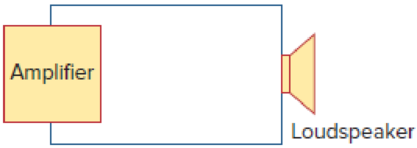
Figure 2.139
Expert Solution & Answer
Want to see the full answer?
Check out a sample textbook solution
Students have asked these similar questions
A certain signal f(t) has the following PSD (assume 12 load):
Sp (w) = new + 8(w) - 1.5) + (w + 1.5)]
(a) What is the mean power in the bandwidth w≤2 rad/see?
(b) What is the mean power in the bandwidth -1.9 to 0.99 rad/sec?
Paress(w) dw
2ㅈ
-
(75 Marks)
JA signal (t) is bond
7)(t)(t) and f(t), are band-limited to 1.2 kHz each. These signals are to be
limited to 9.6 kHz, and three other signals
transmitted by means of time-division multiplexing.
Set up scheme for accomplishing this multiplexing requirement, with each signal sampled
at its Nyquist rate.
What must be the speed of the commutator (the output but ram-k bit/sec)?
the minimum band width?
(25 Marks)
Draw the digital modulation outputs, ASK Amplitude Shift Keying) FSK (Frequency Shift
Keying) and PSK (Phase Shift Keying). For baseband and carriet frequency as shown
101
wwwwwwwwwwww
010
BASESAND
basband
CARRIER
Carral
Chapter 2 Solutions
Fundamentals of Electric Circuits
Ch. 2.2 - The essential component of a toaster is an...Ch. 2.2 - For the circuit shown in Fig. 2.9, calculate the...Ch. 2.2 - A resistor absorbs an instantaneous power of 30...Ch. 2.3 - How many branches and nodes does the circuit in...Ch. 2.4 - Find v1 and v2 in the circuit of Fig. 2.22. Figure...Ch. 2.4 - Find vx and vo in the circuit of Fig. 2.24. Figure...Ch. 2.4 - Find vo and io in the circuit of Fig. 2.26. Figure...Ch. 2.4 - Find the current and voltages in the circuit shown...Ch. 2.6 - By combining the resistors in Fig.2.36, find Req....Ch. 2.6 - Find Rab for the circuit in Fig.2.39. Figure 2.39...
Ch. 2.6 - Calculate Geq in the circuit of Fig.2.41. Figure...Ch. 2.6 - Find v1 and v2 in the circuit shown in Fig. 2.43....Ch. 2.7 - Transform the wye network in Fig. 2.51 to a delta...Ch. 2.7 - For the bridge network in Fig. 2.54, find Rab and...Ch. 2.8 - Refer to Fig. 2.55 and assume there are six light...Ch. 2.8 - Following the ammeter setup of Fig. 2.61. design...Ch. 2 - The reciprocal of resistance is: (a) voltage (b)...Ch. 2 - Prob. 2RQCh. 2 - Prob. 3RQCh. 2 - The maximum current that a 2W, 80 k resistor can...Ch. 2 - Prob. 5RQCh. 2 - The current I in the circuit of Fig. 2.63 is: (a)...Ch. 2 - The current I0 of Fig. 2.64 is: (a) 4 A (b) 2 A...Ch. 2 - In the circuit in Fig. 2.65, V is: (a) 30 V (b) 14...Ch. 2 - Which of the circuit in Fig. 2.66 will give you...Ch. 2 - In the circuit of Fig. 2.67, a decrease in R3...Ch. 2 - Design a problem, complete with a solution, to...Ch. 2 - Find the hot resistance of a light bulb rated 60...Ch. 2 - A bar of silicon is 4 cm long with a circular...Ch. 2 - (a) Calculate current i in Fig. 2.68 when the...Ch. 2 - For the network graph in Fig. 2.69. find the...Ch. 2 - In the network graph shown in Fig. 2.70, determine...Ch. 2 - Determine the number of branches and nodes in the...Ch. 2 - Design a problem, complete with a solution, to...Ch. 2 - Find i1, i2, and i3 in Fig. 2.73. Figure 2.73 For...Ch. 2 - Determine i1 and i2 in the circuit of Fig. 2.74....Ch. 2 - In the circuit of Fig. 2.75, calculate V1 and V2....Ch. 2 - In the circuit in Fig. 2.76, obtain v1, v2, and...Ch. 2 - For the circuit in Fig. 2.77, use KCL to find the...Ch. 2 - Given the circuit in Fig. 2.78, use KVL to find...Ch. 2 - Calculate v and ix in the circuit of Fig. 2.79....Ch. 2 - Determine Vo in the circuit in Fig. 2.80. Figure...Ch. 2 - Obtain v1 through v3 in the circuit of Fig. 2.81....Ch. 2 - Find I and V in the circuit of Fig. 2.82. Figure...Ch. 2 - From the circuit in Fig. 2.83, find I, the power...Ch. 2 - Determine io in the circuit of Fig. 2.84. Figure...Ch. 2 - Find Vx in the circuit of Fig. 2.85. Figure 2.85...Ch. 2 - Find Vo in the circuit in Fig. 2.86 and the power...Ch. 2 - In the circuit shown in Fig. 2.87, determine Vx...Ch. 2 - For the circuit in Fig. 2.88, find Vo/Vs in terms...Ch. 2 - For the network in Fig. 2.89, find the current,...Ch. 2 - For the circuit in Fig. 2.90, io = 3 A. Calculate...Ch. 2 - Calculate Io in the circuit of Fig. 2.91. Figure...Ch. 2 - Design a problem, using Fig. 2.92, to help other...Ch. 2 - All resistors (R) in Fig. 2.93 are 10 each. Find...Ch. 2 - For the circuit in Fig. 2.95, determine i1 to i5....Ch. 2 - Find i1 through i4 in the circuit in Fig. 2.96....Ch. 2 - Obtain v and i in the circuit of Fig. 2.97. Figure...Ch. 2 - Using series/parallel resistance combination, find...Ch. 2 - Calculate Vo and Io in the circuit of Fig. 2.99....Ch. 2 - Find i and Vo in the circuit of Fig. 2.100. Figure...Ch. 2 - Given the circuit in Fig. 2.101 and that the...Ch. 2 - Find Req and io in the circuit of Fig. 2.102....Ch. 2 - Evaluate Req looking into each set of terminals...Ch. 2 - For the ladder network in Fig. 2.104, find I and...Ch. 2 - If Req = 50 in the circuit of Fig. 2.105, find R....Ch. 2 - Reduce each of the circuits in Fig. 2.106 to a...Ch. 2 - Calculate the equivalent resistance Rab at...Ch. 2 - For the circuits in Fig. 2.108, obtain the...Ch. 2 - Find the equivalent resistance at terminals a-b of...Ch. 2 - Find I in the circuit of Fig. 2.110. Figure 2.110Ch. 2 - Find the equivalent resistance Rab in the circuit...Ch. 2 - Convert the circuits in Fig. 2.112 from Y to ....Ch. 2 - Transform the circuits in Fig. 2.113 from to Y....Ch. 2 - Design a problem to help other students better...Ch. 2 - Obtain the equivalent resistance at the terminals...Ch. 2 - For the circuit shown in Fig. 2.116, find the...Ch. 2 - Obtain the equivalent resistance Rab in each of...Ch. 2 - Consider the circuit in Fig. 2.118. Find the...Ch. 2 - Calculate I0 in the circuit of Fig. 2.119. Figure...Ch. 2 - Determine V in the circuit of Fig. 2.120. Figure...Ch. 2 - Find Req and I in the circuit of Fig. 2.121....Ch. 2 - The 150 W tight bulb in Fig. 2.122 is rated at 110...Ch. 2 - If the three bulbs of Prob. 2.59 are connected in...Ch. 2 - As a design engineer, you are asked to design a...Ch. 2 - Prob. 62PCh. 2 - If an ammeter with an internal resistance of 100 ...Ch. 2 - The potentiometer (adjustable resistor) Rx in Fig....Ch. 2 - Design a circuit that uses a dArsonval meter (with...Ch. 2 - A 20-k/V voltmeter reads 10 V full scale. (a) What...Ch. 2 - (a) Obtain the voltage Vo in the circuit of Fig....Ch. 2 - (a) Find the current I in the circuit of Fig....Ch. 2 - A voltmeter used to measure Vo in the circuit in...Ch. 2 - (a) Consider the Wheatstone bridge shown in Fig....Ch. 2 - Figure 2.131 represents a model of a solar...Ch. 2 - Find Vo in the two-way power divider circuit in...Ch. 2 - An ammeter model consists of an ideal ammeter in...Ch. 2 - The circuit in Fig. 2.134 is to control the speed...Ch. 2 - Find Rab in the four-way power divider circuit in...Ch. 2 - Repeat Prob. 2.75 for the eight-way divider shown...Ch. 2 - Suppose your circuit laboratory has the following...Ch. 2 - In the circuit in Fig. 2.137, the wiper divides...Ch. 2 - Prob. 79CPCh. 2 - A loudspeaker is connected to an amplifier as...Ch. 2 - For a specific application, the circuit shown in...Ch. 2 - The pin diagram of a resistance array is shown in...Ch. 2 - Two delicate devices are rated as shown in Fig....
Knowledge Booster


Learn more about
Need a deep-dive on the concept behind this application? Look no further. Learn more about this topic, electrical-engineering and related others by exploring similar questions and additional content below.Similar questions
- please show full working. I've included the solutionarrow_forwardcan you please show working and steps. The answer is 8kohms.arrow_forwardPSD A certain signal f(t) has the following PSD (assume 12 load): | Sƒ(w) = π[e¯\w\ + 8(w − 2) + +8(w + 2)] (a) What is the mean power in the bandwidth w≤ 1 rad/sec? (b) What is the mean power in the bandwidth 0.99 to 1.01 rad/sec? (c) What is the mean power in the bandwidth 1.99 to 2.01 rad/sec? (d) What is the total mean power in (t)? Pav= + 2T SfLw) dw - SALW)arrow_forward
- An AM modulation waveform signal:- p(t)=(8+4 cos 1000πt + 4 cos 2000πt) cos 10000nt (a) Sketch the amplitude spectrum of p(t). (b) Find total power, sideband power and power efficiency. (c) Find the average power containing of each sideband.arrow_forwardCan you rewrite the solution because it is unclear? AM (+) = 8(1+ 0.5 cos 1000kt +0.5 ros 2000ks) = cos 10000 πt. 8 cos wat + 4 cos wit + 4 cos Wat coswet. -Jet jooort J11000 t = 4 e jqooort jgoort +4e + e +e j 12000rt. 12000 kt + e +e jooxt igoo t te (w) = 8ES(W- 100007) + 8IS (W-10000) USBarrow_forwardCan you rewrite the solution because it is unclear? AM (+) = 8(1+0.5 cos 1000kt +0.5 ros 2000 thts) = cos 10000 πt. 8 cos wat + 4 cos wit + 4 cos Wat coswet. J4000 t j11000rt $14+) = 45 jqooort +4e + e + e j 12000rt. 12000 kt + e +e +e Le jsoort -; goon t te +e Dcw> = 885(W- 100007) + 8 IS (W-10000) - USBarrow_forward
- Can you rewrite the solution because it is unclear? Q2 AM ①(+) = 8 (1+0.5 cos 1000πt +0.5 ros 2000kt) $4+) = 45 = *cos 10000 πt. 8 cos wat + 4 cosat + 4 cos Wat coswet. j1000016 +4e -j10000πt j11000Rt j gooort -j 9000 πt + e +e j sooort te +e J11000 t + e te j 12000rt. -J12000 kt + с = 8th S(W- 100007) + 8 IS (W-10000) <&(w) = USB -5-5 -4-5-4 b) Pc 2² = 64 PSB = 42 + 4 2 Pt Pc+ PSB = y = Pe c) Puss = PLSB = = 32 4² = 8 w 32+ 8 = × 100% = 140 (1)³×2×2 31 = 20% x 2 = 3w 302 USB 4.5 5 5.6 6 ms Ac = 4 mi = 0.5 mz Ac = 4 ५ M2 = =0.5arrow_forwardA. Draw the waveform for the following binary sequence using Bipolar RZ, Bipolar NRZ, and Manchester code. Data sequence= (00110100) B. In a binary PCM system, the output signal-to-quantization ratio is to be hold to a minimum of 50 dB. If the message is a single tone with fm-5 kHz. Determine: 1) The number of required levels, and the corresponding output signal-to-quantizing noise ratio. 2) Minimum required system bandwidth.arrow_forwardFind Io using Mesh analysisarrow_forward
- FM station of 100 MHz carrier frequency modulated by a 20 kHz sinusoid with an amplitude of 10 volt, so that the peak frequency deviation is 25 kHz determine: 1) The BW of the FM signal. 2) The approximated BW if the modulating signal amplitude is increased to 50 volt. 3) The approximated BW if the modulating signal frequency is increased by 70%. 4) The amplitude of the modulating signal if the BW is 65 kHz.arrow_forwardAn FDM is used to multiplex two groups of signals using AM-SSB, the first group contains 25 speech signals, each has maximum frequency of 4 kHz, the second group contains 15 music signals, each has maximum frequency of 10 kHz. A guard bandwidth of 500 Hz is used bety each two signals and before the first one. 1. Find the BWmultiplexing 2. Find the BWtransmission if the multiplexing signal is modulated using AM-DSB-LC.arrow_forwardAn FM signal with 75 kHz deviation, has an input signal-to-noise ratio of 18 dB, with a modulating frequency of 15 kHz. 1) Find SNRO at demodulator o/p. 2) Find SNRO at demodulator o/p if AM is used with m=0.3. 3) Compare the performance in case 1) and 2).. Hint: for single tone AM-DSB-LC, SNR₁ = (2m²) (4)arrow_forward
arrow_back_ios
SEE MORE QUESTIONS
arrow_forward_ios
Recommended textbooks for you
 Delmar's Standard Textbook Of ElectricityElectrical EngineeringISBN:9781337900348Author:Stephen L. HermanPublisher:Cengage Learning
Delmar's Standard Textbook Of Electricity
Electrical Engineering
ISBN:9781337900348
Author:Stephen L. Herman
Publisher:Cengage Learning
Kirchhoff's Rules of Electrical Circuits; Author: Flipping Physics;https://www.youtube.com/watch?v=d0O-KUKP4nM;License: Standard YouTube License, CC-BY