
Concept explainers
Videos
Obtain the equivalent resistance Rab in each of the circuits of Fig. 2.117. In (b), all resistors have a value of 30 Ω.
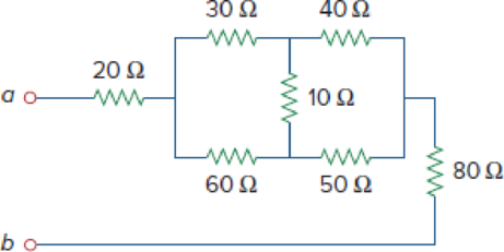
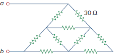
Figure 2.117
(a)
Calculate the equivalent resistor at terminals a-b in Figure 2.117(a).
Answer to Problem 53P
The equivalent resistor at terminals a-b in Figure 2.117(a) is
Explanation of Solution
Formula used:
Consider the delta to wye conversions.
Here,
Consider the expression for
Here,
Consider the expression for
Calculation:
Refer to Figure 2.117(a) in the textbook For Prob.2.53.
Step 1:
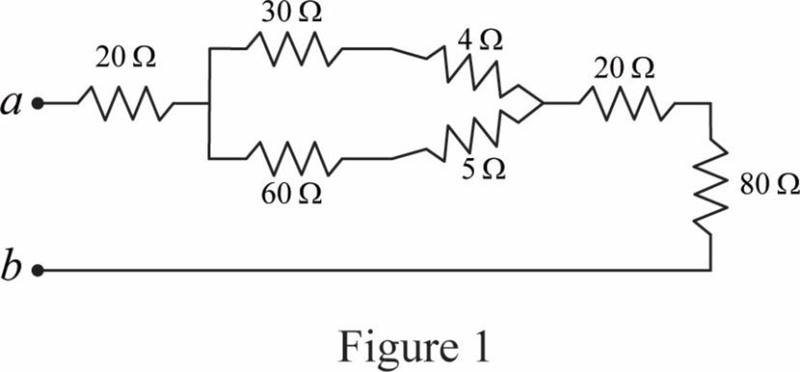
In Figure 2.117(a), convert the delta connection into wye connection.
Consider
Substitute
Substitute
Substitute
Modify Figure 2.117(a) as shown in Figure 1.
Step 2:
In Figure 1, as
Step 3:
In Figure 1, as
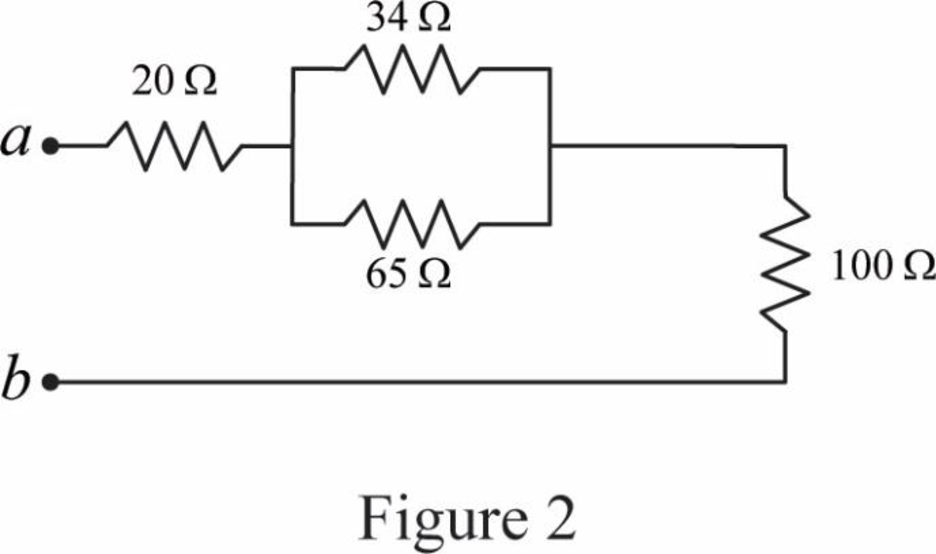
Step 4:
In Figure 1, as
Modify Figure 1 as shown in Figure 2.
Step 5:
In Figure 2, as
Modify Figure 2 as shown in Figure 3.
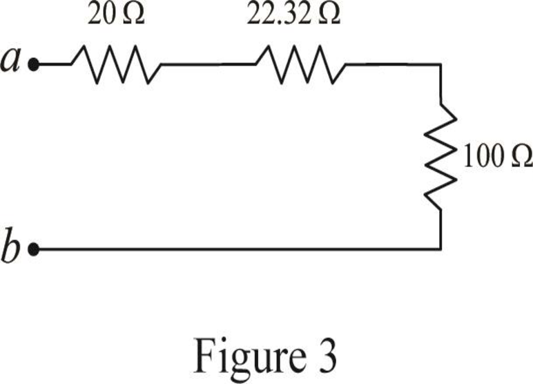
Step 6:
In Figure 3, as
Conclusion:
Thus, the equivalent resistor at terminals a-b in Figure 2.117(a) is
(b)
Calculate the equivalent resistor at terminals a-b in Figure 2.117(b).
Answer to Problem 53P
The equivalent resistor at terminals a-b in Figure 2.117(b) is
Explanation of Solution
Given data:
All resistance have
Formula used:
Consider the following delta to wye conversion, when all branches in a delta consist same value.
Calculation:
Refer to Figure 2.117(b) in the textbook For Prob.2.53.
Step 1:
In Figure 2.117(b), at left most corner of circuit, as two resistors are connected in series, therefore the equivalent resistance for series connected circuit is calculated as follows.
Step 2:
As
Modify Figure 2.117(b) as shown in Figure 4.
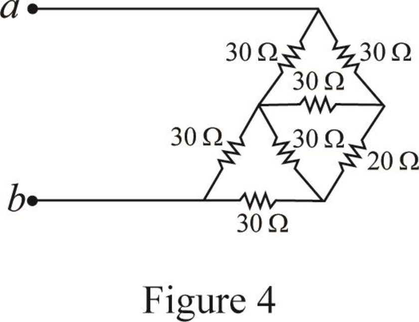
Step 3:
In Figure 4, as in upper part of the circuit all three
Substitute
Since all branch values are same in a delta connection that is
Modify Figure 4 as shown in Figure 5.
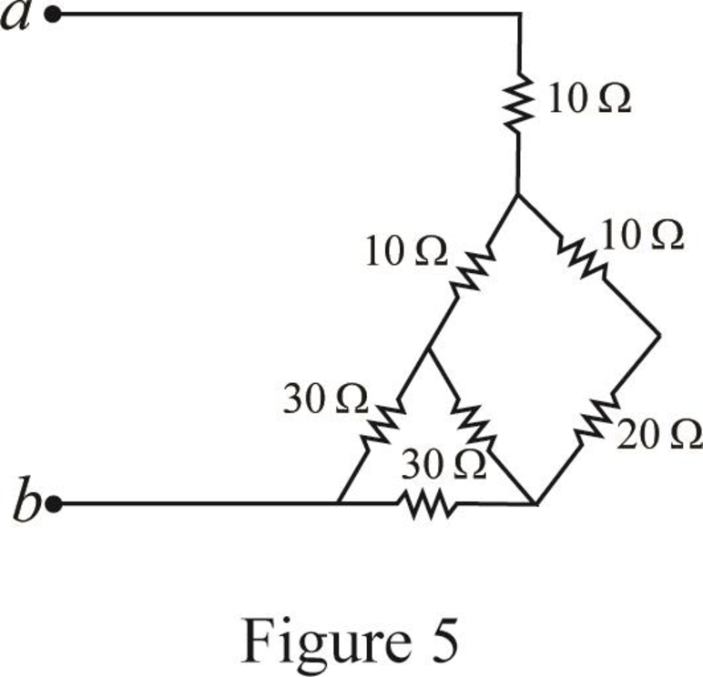
Step 4:
In Figure 5, as
Step 5:
In Figure 5, as in right most part of the circuit all three
Substitute
Since all branch values are same in a delta connection that is
Modify Figure 5 as shown in Figure 6.
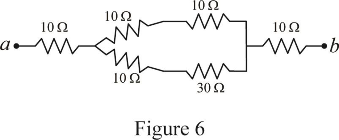
Step 6:
In Figure 6, as
Step 7:
In Figure 6, as
Step 8:
As
Modify Figure 6 as shown in Figure 7.
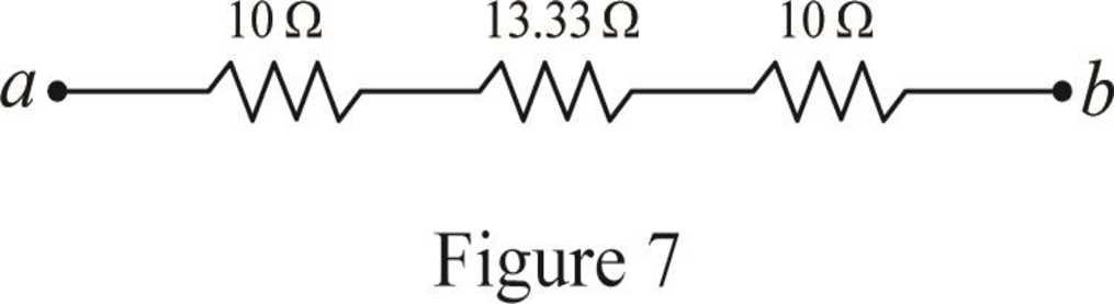
Step 4:
In Figure 7, as
Conclusion:
Thus, the equivalent resistor at terminals a-b in Figure 2.117(b) is
Want to see more full solutions like this?
Chapter 2 Solutions
Fundamentals of Electric Circuits
Additional Engineering Textbook Solutions
Modern Database Management
Mechanics of Materials (10th Edition)
Starting Out With Visual Basic (8th Edition)
Vector Mechanics for Engineers: Statics and Dynamics
Database Concepts (8th Edition)
Electric Circuits. (11th Edition)


- Circuits help please solve and explain. Question in images providedarrow_forward+ V 6.2 A 1.2 A S R 4 Ω Find the source voltage Vs 0.8 Aarrow_forwardDetermine i(t) for t≥ 0 given that the circuit below had been in steady state for a long time prior to t = 0. Also, I₁ = 1 5 A, R₁ =22, R2 =10 Q2, R3 = 32, R4 =7 2, and L=0.15 H. Also fill the table. m L ww R2 t = 0 R₁ 29 R3 R4 Time 0 iL(t) 0 8arrow_forward
- Find the Thévenin equivalent circuit for the portions of the networks in Figure external to the elements between points a and b. a R₁ 2002 I = 0.1 A 0° Xc : 32 Ω R2 = 6802 20 Ω фъarrow_forwardFind the Norton equivalent circuit for the network external to the elements between a and b for the networks in Figure. E1 = 120 V Z 0° R ww 10 Ω Xc XL · 000 802 802 ① I = 0.5 AZ 60° ZL barrow_forwardUsing superposition, determine the current through inductance XL for each network in Figure I = 0.3 A 60° XL 000 802 XC 502 Ω E 10 V0° =arrow_forward
- Find the Thévenin equivalent circuit for the portions of the networks in Figure external to the elements between points a and b. E = 20 VZ0° + R ww 2 ΚΩ Хо XL 000 6ΚΩ 3 ΚΩ b RLarrow_forwardWhat percentage of the full-load current of a thermally protected continuous-duty motor of more than one Hp can the trip current be, if the full-load current is 15 amperes? Ο 122 Ο 140 156 O 170arrow_forwardQ3arrow_forward
 Introductory Circuit Analysis (13th Edition)Electrical EngineeringISBN:9780133923605Author:Robert L. BoylestadPublisher:PEARSON
 Delmar's Standard Textbook Of ElectricityElectrical EngineeringISBN:9781337900348Author:Stephen L. HermanPublisher:Cengage Learning
 Programmable Logic ControllersElectrical EngineeringISBN:9780073373843Author:Frank D. PetruzellaPublisher:McGraw-Hill Education
 Fundamentals of Electric CircuitsElectrical EngineeringISBN:9780078028229Author:Charles K Alexander, Matthew SadikuPublisher:McGraw-Hill Education
 Electric Circuits. (11th Edition)Electrical EngineeringISBN:9780134746968Author:James W. Nilsson, Susan RiedelPublisher:PEARSON
 Engineering ElectromagneticsElectrical EngineeringISBN:9780078028151Author:Hayt, William H. (william Hart), Jr, BUCK, John A.Publisher:Mcgraw-hill Education,