
Concept explainers
Videos
Suppose that you wanted to machine cast iron with BHN of 275. The process to be used is face milling and an HSS cutter is going to be used. What feed and speed values would you select?
Feed and speed value for the face milling.
Explanation of Solution
Given:
Part is cast iron.
Hardness number is 275.
Face milling with HSS cutter is used.
Cutting speed and feed per tooth for the milling operation is selected by the tool operator or engineer. These cutting velocity and feed depends on tool material, specific process and work material.
Following tables shows the cutting speed and fee for different material, cutter and milling process:
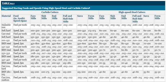
From above table,
Feed can be selected for cast iron is 0.005 − 0.012.
Cutting velocity can be selected for the cast iron as 20-35 fpm.
Want to see more full solutions like this?
Chapter 24 Solutions
Degarmo's Materials And Processes In Manufacturing
Additional Engineering Textbook Solutions
Starting Out with Java: From Control Structures through Objects (7th Edition) (What's New in Computer Science)
Computer Science: An Overview (13th Edition) (What's New in Computer Science)
Starting Out with Java: From Control Structures through Data Structures (4th Edition) (What's New in Computer Science)
Java: An Introduction to Problem Solving and Programming (8th Edition)
Electric Circuits. (11th Edition)
Thermodynamics: An Engineering Approach


- (Read image)arrow_forward(Read Image)arrow_forwardM16x2 grade 8.8 bolts No. 25 C1- Q.2. The figure is a cross section of a grade 25 cast-iron pressure vessel. A total of N, M16x2.0 grade 8.8 bolts are to be used to resist a separating force of 160 kN. (a) Determine ks, km, and C. (b) Find the number of bolts required for a load factor of 2 where the bolts may be reused when the joint 19 mm is taken apart. (c) with the number of bolts obtained in (b), determine the realized load factor for overload, the yielding factor of safety, and the separation factor of safety. 19 mmarrow_forward
- Problem4. The thin uniform disk of mass m = 1-kg and radius R = 0.1m spins about the bent shaft OG with the angular speed w2 = 20 rad/s. At the same time, the shaft rotates about the z-axis with the angular speed 001 = 10 rad/s. The angle between the bent portion of the shaft and the z-axis is ẞ = 35°. The mass of the shaft is negligible compared to the mass of the disk. a. Find the angular momentum of the disk with respect to point G, based on the axis orientation as shown. Include an MVD in your solution. b. Find the angular momentum of the disk with respect to point O, based on the axis orientation as shown. (Note: O is NOT the center of fixed-point rotation.) c. Find the kinetic energy of the assembly. z R R 002 2R x Answer: H = -0.046ĵ-0.040 kg-m²/sec Ho=-0.146-0.015 kg-m²/sec T 0.518 N-m =arrow_forwardProblem 3. The assembly shown consists of a solid sphere of mass m and the uniform slender rod of the same mass, both of which are welded to the shaft. The assembly is rotating with angular velocity w at a particular moment. Find the angular momentum with respect to point O, in terms of the axes shown. Answer: Ñ。 = ½mc²wcosßsinßĵ + (}{mr²w + 2mb²w + ½ mc²wcos²ß) k 3 m r b 2 C لا marrow_forwardOnly question 2arrow_forward
- Only question 1arrow_forwardOnly question 3arrow_forwardI have Euler parameters that describe the orientation of N relative to Q, e = -0.7071*n3, e4 = 0.7071. I have Euler parameters that describe the orientation of U relative to N, e = -1/sqrt(3)*n1, e4 = sqrt(2/3). After using euler parameter rule of successive rotations, I get euler parameters that describe the orientation of U relative to Q, e = -0.4082*n1 - 0.4082*n2 - 0.5774*n3. I need euler parameters that describe the orientation of U relative to Q in vector basis of q instead of n. How do I get that?arrow_forward
- Describe at least 4 processes in engineering where control charts are (or should be) appliedarrow_forwardDescribe at least two (2) processes where control charts are (or should be) applied.arrow_forwardProblem 3: A cube-shaped spacecraft is in a circular Earth orbit. Let N (n,) be inertial and the spacecraft is denoted S (ŝ₁). The spacecraft is described such that ¯½º = J ŝ₁ŝ₁ + J ŝ₂§₂ + J §¸Ŝ3 Location of the spacecraft in the orbit is determined by the orbit-fixed unit vectors ê, that are oriented by the angle (Qt), where is a constant angular rate. 52 €3 3> 2t 55 Λ Из At the instant when Qt = 90°, the spacecraft S is oriented relative to the orbit such that 8₁ = 0° Space-three 1-2-3 angles 0₂ = 60° and ES = $₂ rad/s 0₁ = 135° (a) At this instant, determine the direction cosine matrix that describes the orientation of the spacecraft with respect to the inertial frame N.arrow_forward
 Precision Machining Technology (MindTap Course Li...Mechanical EngineeringISBN:9781285444543Author:Peter J. Hoffman, Eric S. Hopewell, Brian JanesPublisher:Cengage Learning