
Concept explainers
Videos
When travelers from the USA and Canada visit Europe, they encounter a different power distribution system. Wall voltages in North America are 120 V rms at 60 Hz, while typical wall voltages in Europe are 230 V at 50 Hz. Many travelers carry small step-up/step-down transformers so that they can use their appliances in the countries that they are visiting. A typical transformer might be rated at 1 kVA and 115/230 V. It has 500 turns of wire on the 115-V side and 1000 turns of wire on the 230-V side. The magnetization curve for this transformer is shown in Figure P2-2, and can be found in file p22 . mag at this book’s website.
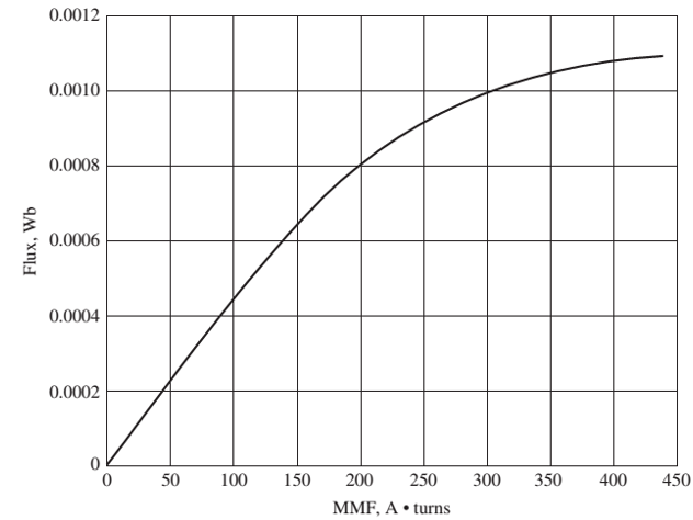
FIGURE P2-2
Magnetization curve for the transformer of Problem 2-5.
- Suppose that this transformer is connected to a 120-V, 60-Hz power source with no load connected to the 240-V side. Sketch the magnetization current that would flow in the transformer. (Use MATLAB to plot the current accurately, if it is available.) What is the rms amplitude of the magnetization current? What percentage of full-load current is the magnetization current?
- Now suppose that this transformer is connected to a 240-V, 50-Hz power source with no load connected to the 120-V side. Sketch the magnetization current that would flow in the transformer. (Use MATLAB to plot the current accurately, if it is available.) What is the rms amplitude of the magnetization current? What percentage of full-load current is the magnetization current?
- In which case is the magnetization current a higher percentage of full-load current? Why?
Want to see the full answer?
Check out a sample textbook solution
Chapter 2 Solutions
Electric machinery fundamentals
Additional Engineering Textbook Solutions
Database Concepts (8th Edition)
HEAT+MASS TRANSFER:FUND.+APPL.
Mechanics of Materials (10th Edition)
Elementary Surveying: An Introduction To Geomatics (15th Edition)
SURVEY OF OPERATING SYSTEMS
Vector Mechanics for Engineers: Statics and Dynamics


- I need help with this problem and an explanation of the solution for the image described below. (Introduction to Signals and Systems)arrow_forwardIn the op-amp circuit shown in Fig. P8.32,uin(t) = 12cos(1000t) V,R = 10 k Ohm , RL = 5 k Ohm, and C = 1 μF. Determine the complexpower for each of the passive elements in the circuit. Isconservation of energy satisfied?arrow_forward2-4) Similar to Lathi & Ding prob. 2.9-4 (a) For signal g(t)=t, find the exponential Fourier series to represent g(t) over the interval(0, 1). (b) Sketch the original signal g(t) and the everlasting signal g'(t) represented by the same Fourier series. (c) Verify Parseval's theorem [eq. (2.103b)] for g'(t), given that: = n 1 6arrow_forward
- 8.24 In the circuit of Fig. P8.24, is(t) = 0.2sin105t A,R = 20 W, L = 0.1 mH, and C = 2 μF. Show that the sum ofthe complex powers for the three passive elements is equal to thecomplex power of the source.arrow_forward3. VEB (on) 0.7 V, VEC (sat) = 0.2 V, and ẞ = 150. RB = 50 kQ, Rc = 2 kQ, and Vcc = 5 V. a) Find the range of V₁ for the cut-off. Forward active, and saturation regions. (20 points) b) Draw the voltage transfer characteristic (VTC) graph. (10 points) Vcc VEB V₁ RB www 。 Vo Rc Figure 3arrow_forward2-1) Lathi & Ding prob. 2.5-2 For the signals y(t) and x(t) shown below, find the component of the form y(t) contained in x(t). In other words, find the optimum value of c in the approximation x(t) = cy(t) so that the error signal energy is minimum. Also compute the error signal energy. y(t) x(t) 0 1 0 1arrow_forward
- 1. Is1 = 2ls2 = 4 × 10-16 A, B₁ = ẞ2 = 100, and R₁ = 5 kQ. Find the VB such that lx = 1 mA. (30 points) R1 ww Q2 + VB Figure 1arrow_forward2-2) Lathi & Ding prob. 2.6-1 2.6-1 Find the correlation coefficient p between of signal x(t) and each of the four pulses g1(1), 82(1), 83(1), and g4(f) shown in Fig. P2.6-1. To provide maximum margin against the noise along the transmission path, which pair of pulses would you select for a binary communication? Figure P.2.6-1 x(f) (a) 8(1) (b) 82(1) (c) 1 1 sin 2πt sin 4πt -sin 2 0 0.707 83(1) 0 1 (d) 0 M P 0.707 84(1) (e) 0 0.5 -0.707arrow_forward2. Determine the operation point and the small-signal model of Q₁ for each of the circuits shown in Fig. 2. Assume Is = 8 × 10-16 A, B = 100 and VA = ∞. a) 20 points b) 20 points 0.8 V RC 50 Ω + Vcc = 2.5 V 4A" Figure 2-a Rc1kQ + Vcc = 2.5 V Figure 2-barrow_forward
 Power System Analysis and Design (MindTap Course ...Electrical EngineeringISBN:9781305632134Author:J. Duncan Glover, Thomas Overbye, Mulukutla S. SarmaPublisher:Cengage Learning
 Electricity for Refrigeration, Heating, and Air C...Mechanical EngineeringISBN:9781337399128Author:Russell E. SmithPublisher:Cengage Learning
 Delmar's Standard Textbook Of ElectricityElectrical EngineeringISBN:9781337900348Author:Stephen L. HermanPublisher:Cengage Learning