
Electric machinery fundamentals
5th Edition
ISBN: 9780073529547
Author: Chapman, Stephen J.
Publisher: MCGRAW-HILL HIGHER EDUCATION
expand_more
expand_more
format_list_bulleted
Concept explainers
Videos
Textbook Question
Chapter 2, Problem 2.23P
A single-phase, 10-kVA, 480/120-V transformer is to be used as an autotransformer tying a 600-V distribution line to a 480-V load. When it is tested as a conventional transformer, the following values are measured on the primary (480-V) side of the transformer:
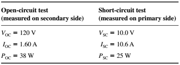
- Find the per-unit equivalent circuit of this transformer when it is connected in the conventional manner. What is the efficiency of the transformer at rated conditions and unity power factor? What is the voltage regulation at those conditions?
- Sketch the transformer connections when it is used as a 600/480-V step-down autotransformer.
- What is the kilovoltampere rating of this transformer when it is used in the autotransformer connection?
- Answer the questions in (a) for the autotransformer connection.
Expert Solution & Answer

Trending nowThis is a popular solution!

Students have asked these similar questions
b)
A 132 kV supply feeds a line of reactance 15 which is connected to a 100
MVA, 132/33 kV transformer of 0.08 p.u. reactance as shown in the
Figure 2. The transformer feeds a 33 kV line of reactance 8 Q, which, in
turn, is connected to a 75 MVA, 33/11 KV transformer of 0.12 p.u.
reactance. The transformer supplies an 11 KV substation from which a local
11 kV feeder of 4 Q reactance is supplied.
T1
T2
132 kV
33 kV
11 kV
Fault
X
CB
Relay
Figure 2. Network for Q4 b).
(i) Given the system base of 100 MVA, compute the total equivalent
reactance of the radial circuit in per unit (p.u.).
(ii) Determine the three-phase fault current at the load end of the 11 kV
feeder, assuming a fault impedance of 0.05 Q. Calculate the fault
current in Amperes.
(iii) The 11 kV feeder connects to a protective overcurrent relay via 200/5 A
current transformers. This relay has a standard normally inverse IDMT
characteristic, with a setting current of 3 A and a time multiplier setting
of 0.4. Calculate the…
Q2.
a) Two three-phase transformers, designated A and B, have the following
secondary equivalent circuit parameters per phase:
R₁ = 0.002 Q, XA = 0.03 Q, RB = 0.004 Q, X = 0.012 Q
Transformer A is 250 kVA and transformer B is 450 kVA. Calculate how
they share a load of 650 KVA when connected in parallel (assume the
voltage ratios are equal)
b) A step-up transformer is being specified for the beginning of a 3-phase, 4
wire high voltage transmission line. Discuss your recommendation for the
configuration of the transformer connections on both the primary and
secondary side of the transformer.
c)
Define power system protection and describe its fundamental purpose.
Discuss the following key concepts including discrimination, stability,
speed of operation, sensitivity, and reliability in the context of the power
system protection components and schemes.
Q3.
a) Given the unsymmetrical phasors for a three-phase system, they can be
represented in terms of their symmetrical components as follows:
[Fa]
[1 1
Fb = 1 a²
[Fc.
11[Fao]
a Fai
1 a a2F a2-
where F stands for any three-phase quantity. Conversely, the sequence
components can be derived from the unsymmetrical phasors as:
[11 1] [Fal
Faol
Fa1 =
1 a a² F
1 a²
a
a2.
Given the unbalanced three-phase voltages:
V₁ = 120/10° V, V₂ = 200/110° V, V = 240/200° V
Calculate in polar form the sequence components of the voltage.
Chapter 2 Solutions
Electric machinery fundamentals
Ch. 2 - Is the turns ratio of a transformer the same as...Ch. 2 - Why does the magnetization current impose an upper...Ch. 2 - What components compose the excitation current of...Ch. 2 - What is the leakage flux in a transformer? Why is...Ch. 2 - List and describe the types of losses that occur...Ch. 2 - Why does the power factor of a load affect the...Ch. 2 - Why does the short-circuit test essentially show...Ch. 2 - Why does the open-circuit test essentially show...Ch. 2 - How does the per-unit system of measurement...Ch. 2 - Why can autotransformers handle more power than...
Ch. 2 - What are transformer taps? Why are they used?Ch. 2 - What are the problems associated with the Y—Y...Ch. 2 - What is a TCUL transformer?Ch. 2 - How can three-phase transformation be accomplished...Ch. 2 - Prob. 2.15QCh. 2 - Can a 60-Hz transformer be operated on a 50-Hz...Ch. 2 - What happens to a transformer when it is first...Ch. 2 - What is a potential transform? How is it used?Ch. 2 - What is a current transformer? How is it used?Ch. 2 - A distribution transformer is rated at 18 kVA,...Ch. 2 - Why does one hear a hum when standing near a large...Ch. 2 - A 100-kVA, 8000/277-V distribution transformer has...Ch. 2 - A single-phase power system is shown in Figure...Ch. 2 - Consider a simple power system consisting of an...Ch. 2 - The secondary winding of a real transformer has a...Ch. 2 - When travelers from the USA and Canada visit...Ch. 2 - A 1000-VA, 230/115-V transformer has been tested...Ch. 2 - A 30-kVA, 8000/230-V distribution transformer has...Ch. 2 - A 150-MVA, 15/200-kV, single-phase power...Ch. 2 - A 5000-kVA, 230/13.8-kV, single-phase power...Ch. 2 - A three-phase transformer bank is to handle 500...Ch. 2 - A 100-MVA, 230/115-kV, Y three-phase power...Ch. 2 - Three 20-kVA, 24,000/277-V distribution...Ch. 2 - A 14,000/480-V, three-phase, Y-connected...Ch. 2 - A 13.8-kV, single-phase generator supplies power...Ch. 2 - An autotransformer is used to connect a 12.6-kV...Ch. 2 - Prove the following statement: If a transformer...Ch. 2 - A 10-kVA, 480/120-V conventional transformer is to...Ch. 2 - A 10-kVA, 480/120-V conventional transformer is to...Ch. 2 - Two phases of a 14.4-kV, three-phase distribution...Ch. 2 - A 50-kVA, 20,000/480-V, 60-Hz, single-phase...Ch. 2 - Prove that the three-phase system of voltages on...Ch. 2 - Prove that the three-phase system of voltages on...Ch. 2 - A single-phase, 10-kVA, 480/120-V transformer is...Ch. 2 - Figure P2-4 shows a one-line diagram of a power...
Knowledge Booster


Learn more about
Need a deep-dive on the concept behind this application? Look no further. Learn more about this topic, electrical-engineering and related others by exploring similar questions and additional content below.Similar questions
- Complete the table of values for this circuit:arrow_forward*P2.58. Solve for the node voltages shown in Figure P2.58. - 10 Ω w + 10 Ω 15 Ω w w '+' 5 Ω 20x 1 A Figure P2.58 w V2 502 12Aarrow_forwardAn 18.65 kW, 4-pole, 50 Hz, 3-phase induction motor has friction and windage losses of 2.5% of the output. The full-load slip is 4%. Find for full-load (i) the rotor cu loss (ii) the rotor input power (iii) the output torque.arrow_forward
- Q1: Consider the finite state machine logic implementation in Fig. shown below: a. b. Construct the state diagram. Repeat the circuit design using j-k flip flop. C'lk A D 10 Clk Q D 32 Cik O 31 Please solve the question on a sheet of paper by hand and explain everything related to the question step by step.arrow_forwardAnot ined sove in peaper S PU +96 An 18.65 kW, 4-pole, 50 Hz, 3-phase induction motor has friction and windage losses of 2.5% of the output. The full-load slip is 4 %. Find for full-load (i) the rotor cu loss (ii) the rotor input power (iii) the output torque. 750 1 T el Marrow_forwardAlternator has star-connected,4-pole, 50 Hz as the following data: Flux per pole-0.12 Wb; No. of slot/pole/phase=4; conductor/slot=4; Each coil spans 150° (electrical degree) pitches Find (i) number of turns per phase (ii) distribution factor (iii) pitch factor (iv) no-load phase voltage (v) no-load line voltage.arrow_forward
- Alternator has star-connected,4-pole, 50 Hz as the following data: Flux per pole-0.12 Wb; No. of slot/pole/phase=4; conductor/slot=4; Each coil spans 150° (electrical degree) pitches Find (i) number of turns per phase (ii) distribution factor (iii) pitch factor (iv) no-load phase voltage (v) no-load line voltage.arrow_forwardA) Suppose you were desiging a circuit that required two LEDs for "power on" indication. The power supply voltage is 5 volts, and each LED is rated at 1.6 volts and 20 mA. Calculate the dropping resistor sizes and power ratings: B) After doing this, a co-worker looks at your circuit and suggests a modification. Why not use a single dropping resistor for both LEDs, economizing the number of components necessary? Re-calculate the dropping resistor ratings (resistance and power) for the new design. Include the total power consumed by the circuit and the power delivered by the source.arrow_forwardS A L ined sove in peaper ۳/۱ 16852 Alternator has star-connected,4-pole, 50 Hz as the following data: Flux per pole-0.12 Wb; No. of slot/pole/phase-4; conductor/slot-4; Each coil spans 150° (electrical degree) pitches Find (i) number of turns per phase (ii) distribution factor (iii) pitch factor (iv) no-load phase voltage (v) no-load line voltage. 2ci25 750 r 2.01 ४arrow_forward
- A) Complete the table of values for this circuit: B) Draw the schematic include polarityarrow_forward(choose R1, R2, R3, R4, R5 and assume that 300 β = , all resistors must be greater than zero) such that the following specifications are met: • Minimum open loop gain, Aol, 40dB (can be more, this is the minimum requirement) • Input current (at input terminals) <1uA • Power dissipation DC P ≤20mW • VCC=10V, VEE=0VI NEED HELP, I WANT ONLY TO CALCULATE THE RESISTORSarrow_forward80 V 300 Ω t = 0 500 i(t) Vc(t) 40 nF 2,5 mH -arrow_forward
arrow_back_ios
SEE MORE QUESTIONS
arrow_forward_ios
Recommended textbooks for you
 Power System Analysis and Design (MindTap Course ...Electrical EngineeringISBN:9781305632134Author:J. Duncan Glover, Thomas Overbye, Mulukutla S. SarmaPublisher:Cengage Learning
 Electricity for Refrigeration, Heating, and Air C...Mechanical EngineeringISBN:9781337399128Author:Russell E. SmithPublisher:Cengage Learning
Power System Analysis and Design (MindTap Course ...
Electrical Engineering
ISBN:9781305632134
Author:J. Duncan Glover, Thomas Overbye, Mulukutla S. Sarma
Publisher:Cengage Learning
Electricity for Refrigeration, Heating, and Air C...
Mechanical Engineering
ISBN:9781337399128
Author:Russell E. Smith
Publisher:Cengage Learning
TRANSFORMERS - What They Are, How They Work, How Electricians Size Them; Author: Electrician U;https://www.youtube.com/watch?v=tXPy4OE7ApE;License: Standard Youtube License