
Electric machinery fundamentals
5th Edition
ISBN: 9780073529547
Author: Chapman, Stephen J.
Publisher: MCGRAW-HILL HIGHER EDUCATION
expand_more
expand_more
format_list_bulleted
Concept explainers
Videos
Textbook Question
Chapter 2, Problem 2.1Q
Is the turns ratio of a transformer the same as the ratio of voltages across the transformer? Why or why not?
Expert Solution & Answer
To determine
Whether a transformer’s turns ratio is same as a transformer’s voltage ratio or not along with reason.
Explanation of Solution
Diagram of ideal transformer is:
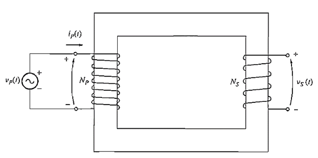
Mutual flux of transformer is
Primary voltage of transformer is
Secondary voltage of transformer is −
Ratio of primary and secondary voltage is
It is observed that ratio of voltages of transformer are same as ratio of their turns because flux linking both the coils is same. So, voltage will be directly proportional to number of turns.
Want to see more full solutions like this?
Subscribe now to access step-by-step solutions to millions of textbook problems written by subject matter experts!
Students have asked these similar questions
microprocers and microcontroler
Design a counter to count-up from 2 to 7 using three of
D Flip Flops
(3) 3-Bit Count up (3 to 5) Using D Flip-Flop:
The State Equation of D Flip-Flop:
Q(t+1)=D(t) => Dn=Qn
Present State
D Flip-Flop
Next State
n
Q2p Q1p Q0p
3
0 1
1
1
Q2n Q1n Q0n D2 D1 D0
0 0 1 0 0
4
1
0
0
1
0
1
1 0
1
5
1 0
1
0
1
1
01
1
D2-Sum(3,4) and don't care X-Sum(0,1,2,6,7)
D1=Sum(5) and don't care X=Sum(0,1,2,6,7)
D0=Sum(4,5) and don't care X=Sum(0,1,2,6,7)
Using K-map to simplify the functions:
D2=Q1+Q0'
D1=Q1'QO
DO=Q1'
XOX
XOX
Q2 10
Q2 01
Q2 1xx
Q0
QO
Qo
D2 Q2
>CK
Q2
D1 Q1
BCD
CK
Q1
DO QF
►CK
Q0
☐ Present State Next State D Flip-Flop
n Q2p Q1p Q0p Q2n Q1n Q0n D2 D1 D0
2 0 1
0
0 1 1 0 1 1
3 0
1
1
1
0
0 1 00
4
1
0
0
1
0
1
1
0
1
5
1
0
1
1
1
0
1 1
0
6
1
1
0
0
1
0
0
1
0
D2
D2=Sum(3,4,5), X=Sum(0,1,7)
D1
Q2
1
Q1
1
0
☑
0
Qo
D2=Q0+Q1'
✗
0
Q1
Consider the following 4×1 multiplexer with inputs:
w0=2, w1=1, w2=x2' and w3=0
And with switches:
S1 x1 and S0=x0
What is the multiplexer output f as a function of x2, x1
and x0?
Chapter 2 Solutions
Electric machinery fundamentals
Ch. 2 - Is the turns ratio of a transformer the same as...Ch. 2 - Why does the magnetization current impose an upper...Ch. 2 - What components compose the excitation current of...Ch. 2 - What is the leakage flux in a transformer? Why is...Ch. 2 - List and describe the types of losses that occur...Ch. 2 - Why does the power factor of a load affect the...Ch. 2 - Why does the short-circuit test essentially show...Ch. 2 - Why does the open-circuit test essentially show...Ch. 2 - How does the per-unit system of measurement...Ch. 2 - Why can autotransformers handle more power than...
Ch. 2 - What are transformer taps? Why are they used?Ch. 2 - What are the problems associated with the Y—Y...Ch. 2 - What is a TCUL transformer?Ch. 2 - How can three-phase transformation be accomplished...Ch. 2 - Prob. 2.15QCh. 2 - Can a 60-Hz transformer be operated on a 50-Hz...Ch. 2 - What happens to a transformer when it is first...Ch. 2 - What is a potential transform? How is it used?Ch. 2 - What is a current transformer? How is it used?Ch. 2 - A distribution transformer is rated at 18 kVA,...Ch. 2 - Why does one hear a hum when standing near a large...Ch. 2 - A 100-kVA, 8000/277-V distribution transformer has...Ch. 2 - A single-phase power system is shown in Figure...Ch. 2 - Consider a simple power system consisting of an...Ch. 2 - The secondary winding of a real transformer has a...Ch. 2 - When travelers from the USA and Canada visit...Ch. 2 - A 1000-VA, 230/115-V transformer has been tested...Ch. 2 - A 30-kVA, 8000/230-V distribution transformer has...Ch. 2 - A 150-MVA, 15/200-kV, single-phase power...Ch. 2 - A 5000-kVA, 230/13.8-kV, single-phase power...Ch. 2 - A three-phase transformer bank is to handle 500...Ch. 2 - A 100-MVA, 230/115-kV, Y three-phase power...Ch. 2 - Three 20-kVA, 24,000/277-V distribution...Ch. 2 - A 14,000/480-V, three-phase, Y-connected...Ch. 2 - A 13.8-kV, single-phase generator supplies power...Ch. 2 - An autotransformer is used to connect a 12.6-kV...Ch. 2 - Prove the following statement: If a transformer...Ch. 2 - A 10-kVA, 480/120-V conventional transformer is to...Ch. 2 - A 10-kVA, 480/120-V conventional transformer is to...Ch. 2 - Two phases of a 14.4-kV, three-phase distribution...Ch. 2 - A 50-kVA, 20,000/480-V, 60-Hz, single-phase...Ch. 2 - Prove that the three-phase system of voltages on...Ch. 2 - Prove that the three-phase system of voltages on...Ch. 2 - A single-phase, 10-kVA, 480/120-V transformer is...Ch. 2 - Figure P2-4 shows a one-line diagram of a power...
Knowledge Booster


Learn more about
Need a deep-dive on the concept behind this application? Look no further. Learn more about this topic, electrical-engineering and related others by exploring similar questions and additional content below.Similar questions
- I need help adding a capacitor and a Zener diode to my circuit. I’m looking for a simple sketch or diagram showing how to connect them. i want diagram with final circuit after adding the zener diad and capacitor. don't do calclution or anything. thanksarrow_forwardQuestion 3 AC Motor Drives [15]Calculate the instantaneous currents delivered by the inverter if the direct axiscurrent required at a particular instant is 8.66A and the quadrature current is5A. Derive all equations for the three currents.arrow_forwardA certain signal f(t) has the following PSD (assume 12 load): Sp (w) = new + 8(w) - 1.5) + (w + 1.5)] (a) What is the mean power in the bandwidth w≤2 rad/see? (b) What is the mean power in the bandwidth -1.9 to 0.99 rad/sec? Paress(w) dw 2ㅈ -arrow_forward
- (75 Marks) JA signal (t) is bond 7)(t)(t) and f(t), are band-limited to 1.2 kHz each. These signals are to be limited to 9.6 kHz, and three other signals transmitted by means of time-division multiplexing. Set up scheme for accomplishing this multiplexing requirement, with each signal sampled at its Nyquist rate. What must be the speed of the commutator (the output but ram-k bit/sec)? the minimum band width? (25 Marks)arrow_forwardDraw the digital modulation outputs, ASK Amplitude Shift Keying) FSK (Frequency Shift Keying) and PSK (Phase Shift Keying). For baseband and carriet frequency as shown 101 wwwwwwwwwwww 010 BASESAND basband CARRIER Carralarrow_forwardplease show full working. I've included the solutionarrow_forward
- can you please show working and steps. The answer is 8kohms.arrow_forwardPSD A certain signal f(t) has the following PSD (assume 12 load): | Sƒ(w) = π[e¯\w\ + 8(w − 2) + +8(w + 2)] (a) What is the mean power in the bandwidth w≤ 1 rad/sec? (b) What is the mean power in the bandwidth 0.99 to 1.01 rad/sec? (c) What is the mean power in the bandwidth 1.99 to 2.01 rad/sec? (d) What is the total mean power in (t)? Pav= + 2T SfLw) dw - SALW)arrow_forwardAn AM modulation waveform signal:- p(t)=(8+4 cos 1000πt + 4 cos 2000πt) cos 10000nt (a) Sketch the amplitude spectrum of p(t). (b) Find total power, sideband power and power efficiency. (c) Find the average power containing of each sideband.arrow_forward
- Can you rewrite the solution because it is unclear? AM (+) = 8(1+ 0.5 cos 1000kt +0.5 ros 2000ks) = cos 10000 πt. 8 cos wat + 4 cos wit + 4 cos Wat coswet. -Jet jooort J11000 t = 4 e jqooort jgoort +4e + e +e j 12000rt. 12000 kt + e +e jooxt igoo t te (w) = 8ES(W- 100007) + 8IS (W-10000) USBarrow_forwardCan you rewrite the solution because it is unclear? AM (+) = 8(1+0.5 cos 1000kt +0.5 ros 2000 thts) = cos 10000 πt. 8 cos wat + 4 cos wit + 4 cos Wat coswet. J4000 t j11000rt $14+) = 45 jqooort +4e + e + e j 12000rt. 12000 kt + e +e +e Le jsoort -; goon t te +e Dcw> = 885(W- 100007) + 8 IS (W-10000) - USBarrow_forwardCan you rewrite the solution because it is unclear? Q2 AM ①(+) = 8 (1+0.5 cos 1000πt +0.5 ros 2000kt) $4+) = 45 = *cos 10000 πt. 8 cos wat + 4 cosat + 4 cos Wat coswet. j1000016 +4e -j10000πt j11000Rt j gooort -j 9000 πt + e +e j sooort te +e J11000 t + e te j 12000rt. -J12000 kt + с = 8th S(W- 100007) + 8 IS (W-10000) <&(w) = USB -5-5 -4-5-4 b) Pc 2² = 64 PSB = 42 + 4 2 Pt Pc+ PSB = y = Pe c) Puss = PLSB = = 32 4² = 8 w 32+ 8 = × 100% = 140 (1)³×2×2 31 = 20% x 2 = 3w 302 USB 4.5 5 5.6 6 ms Ac = 4 mi = 0.5 mz Ac = 4 ५ M2 = =0.5arrow_forward
arrow_back_ios
SEE MORE QUESTIONS
arrow_forward_ios
Recommended textbooks for you
 Electricity for Refrigeration, Heating, and Air C...Mechanical EngineeringISBN:9781337399128Author:Russell E. SmithPublisher:Cengage Learning
 Power System Analysis and Design (MindTap Course ...Electrical EngineeringISBN:9781305632134Author:J. Duncan Glover, Thomas Overbye, Mulukutla S. SarmaPublisher:Cengage Learning
Electricity for Refrigeration, Heating, and Air C...
Mechanical Engineering
ISBN:9781337399128
Author:Russell E. Smith
Publisher:Cengage Learning
Power System Analysis and Design (MindTap Course ...
Electrical Engineering
ISBN:9781305632134
Author:J. Duncan Glover, Thomas Overbye, Mulukutla S. Sarma
Publisher:Cengage Learning
TRANSFORMERS - What They Are, How They Work, How Electricians Size Them; Author: Electrician U;https://www.youtube.com/watch?v=tXPy4OE7ApE;License: Standard Youtube License