
ANALYSIS+DESIGN OF LINEAR CIRCUITS(LL)
8th Edition
ISBN: 9781119235385
Author: Thomas
Publisher: WILEY
expand_more
expand_more
format_list_bulleted
Concept explainers
Videos
Textbook Question
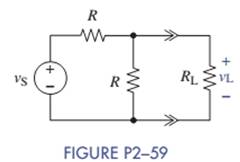
Chapter 2, Problem 2.59P
Use voltage division in Figure P2-59 to obtain an expression for
Expert Solution & Answer
Want to see the full answer?
Check out a sample textbook solution
Students have asked these similar questions
PSD
A certain signal f(t) has the following PSD (assume 12 load):
| Sƒ(w) = π[e¯\w\ + 8(w − 2) + +8(w + 2)]
(a) What is the mean power in the bandwidth w≤ 1 rad/sec?
(b) What is the mean power in the bandwidth 0.99 to 1.01 rad/sec?
(c) What is the mean power in the bandwidth 1.99 to 2.01 rad/sec?
(d) What is the total mean power in (t)?
Pav=
+
2T
SfLw) dw
- SALW)
An AM modulation waveform signal:-
p(t)=(8+4 cos 1000πt + 4 cos 2000πt) cos 10000nt
(a) Sketch the amplitude spectrum of p(t).
(b) Find total power, sideband power and power efficiency.
(c) Find the average power containing of each sideband.
Can you rewrite the solution because it is
unclear?
AM
(+) = 8(1+ 0.5 cos 1000kt +0.5 ros 2000ks)
=
cos 10000 πt.
8 cos wat + 4 cos wit + 4 cos Wat coswet.
-Jet
jooort
J11000 t
= 4 e
jqooort jgoort
+4e
+ e
+e
j 12000rt.
12000 kt
+
e
+e
jooxt
igoo t
te
(w) = 8ES(W- 100007) + 8IS (W-10000)
USB
Chapter 2 Solutions
ANALYSIS+DESIGN OF LINEAR CIRCUITS(LL)
Ch. 2 - Prob. 2.1PCh. 2 - The voltage across a particular resistor is 8.60 V...Ch. 2 - You can choose to connect either a 4.7-k resistor...Ch. 2 - A model railroader wants to be able to...Ch. 2 - A 100-k resistor dissipates 50mW. Find the current...Ch. 2 - The conductance of a particular semiconductor...Ch. 2 - In Figure P2—7 the resistor dissipates 25 mW. Find...Ch. 2 - In Figure P2—8 find Rx and the power supplied by...Ch. 2 - A resistor found in the lab has three orange...Ch. 2 - The iv characteristic of a nonlinear resistor is...
Ch. 2 - A 100-k resistor has a power rating of 0.25 W....Ch. 2 - A certain type of film resistor is available with...Ch. 2 - Figure P2—13 shows the circuit symbol for a class...Ch. 2 - A thermistor is a temperature-sensing element...Ch. 2 - In Figure P2-15i2=6A and i3=2A. Find i1 and i4.Ch. 2 - In Figure P2-16 determine which elements are in...Ch. 2 - For the circuit in Figure P2—17: Identify the...Ch. 2 - In Figure P2-17 i2=30mA and i4=20mA. Find i1 and...Ch. 2 - For the circuit in Figure P2—19: Identify the...Ch. 2 - In Figure P2-19 v2=20V,v3=20V, and v4=6V. Find...Ch. 2 - In many circuits the ground is often the metal...Ch. 2 - The circuit in figure P2-22 is organized around...Ch. 2 - Are any of the elements in Figure P2-23 in series...Ch. 2 - Are any of the elements in Figure P2-24 in series...Ch. 2 - Use the passive sign convention to assign voltage...Ch. 2 - If a wire is connected between nodes B and C in...Ch. 2 - The KCL equations for a three-node circuit are as...Ch. 2 - For the circuit in Figure P2—28, write a complete...Ch. 2 - For the circuit in Figure P2—29, write a complete...Ch. 2 - Find vx and ix in Figure P2-30. Compare the...Ch. 2 - A modeler wants to light his model building using...Ch. 2 - Find vx and ix in Figure P2-32.Ch. 2 - In Figure P2-33: Assign a voltage and current...Ch. 2 - Find vO in the circuit of Figure P2-34.Ch. 2 - Find the power provided by the source in Figure...Ch. 2 - Figure P2-36 shows a subcircuit connected to the...Ch. 2 - In Figure P2-37 ix=0.33mA. Find the value of R.Ch. 2 - Figure P2—38 shows a resistor with one terminal...Ch. 2 - Find the equivalent resistant REQ in Figure P2-39.Ch. 2 - Find the equivalent R EQ in Figure P2-40.Ch. 2 - Find the equivalent resistance REQ in Figure...Ch. 2 - Equivalent resistance is defined at a particular...Ch. 2 - Find REQ in Figure P2—43 when the switch is open....Ch. 2 - Find REQ between nodes A and B for each of the...Ch. 2 - Show how the circuit in Figure P2—45 could be...Ch. 2 - In Figure P2-46 find the equivalent resistance...Ch. 2 - In Figure P2-47 find the equivalent resistance...Ch. 2 - Select a value of RL in Figure P2-48 so that...Ch. 2 - Using no more than four 1-k resistors, show how...Ch. 2 - Do a source transformation at terminals A and B...Ch. 2 - For each of the circuits in Figure P2-51, find the...Ch. 2 - In Figure P2-52, the iv characteristic of network...Ch. 2 - Select the value of Rx in Figure P2-53 so that...Ch. 2 - Two 10-k potentiometers (a variable resistor whose...Ch. 2 - Select the value of R in Figure P2-55 so that...Ch. 2 - What is the range of REQ in Figure P2-56?Ch. 2 - Find the equivalent resistance between terminals A...Ch. 2 - Use voltage division in Figure P2-58 to find...Ch. 2 - Use voltage division in Figure P2-59 to obtain an...Ch. 2 - Use current division in Figure P2-60 to find...Ch. 2 - Use current division in Figure P2-61 to find an...Ch. 2 - Find ix,iy, and iz in Figure P2-62.Ch. 2 - Find vO in the circuit of Figure P2-63.Ch. 2 - You wish to drive a 1-k load from your car battery...Ch. 2 - Find the range of values of vo in Figure P2-65.Ch. 2 - Use current division in the circuit of Figure...Ch. 2 - Figure P2-67 shows a voltage bridge circuit, that...Ch. 2 - A Ideally, a voltmeter has infinite internal...Ch. 2 - Select values for R1,R2, and R3 in Figure P2-69 so...Ch. 2 - Select a value of Rx in Figure P2-70 so that...Ch. 2 - Select a value of Rx in Figure P2-71 so that...Ch. 2 - Use circuit reduction to find vx and ix in Figure...Ch. 2 - Use circuit reduction to find vx,ix, and px in...Ch. 2 - Use circuit reduction to find vx and ix in Figure...Ch. 2 - Use circuit reduction to find vx,ix, and px in...Ch. 2 - Use circuit reduction to find vx and ix in Figure...Ch. 2 - Use source transformation to find ix in Figure...Ch. 2 - Select a value for Rx so that ix=0A in Figure...Ch. 2 - Use source transformations in Figure P2-79 to...Ch. 2 - The current through RL in figure P2-80 is 100mA....Ch. 2 - Select Rx so that 50 V is across it in Figure...Ch. 2 - The box in the circuit in Figure P2-82 is a...Ch. 2 - A circuit is found to have the following element...Ch. 2 - Consider the circuit of Figure P2-88. Use MATLAB...Ch. 2 - Nonlinear Device Characteristics The circuit in...Ch. 2 - Prob. 2.92IPCh. 2 - Center Tapped Voltage Divider Figure P2-93 shows a...Ch. 2 - Active Transducer Figure P2-95 shows an active...Ch. 2 - Programmable Voltage Divider Figure P2-97 shows a...Ch. 2 - Analog Voltmeter Design Figure P2-98(a) shows a...Ch. 2 - MATLAB Function for Parallel Equivalent Resistors...
Knowledge Booster


Learn more about
Need a deep-dive on the concept behind this application? Look no further. Learn more about this topic, electrical-engineering and related others by exploring similar questions and additional content below.Similar questions
- Can you rewrite the solution because it is unclear? AM (+) = 8(1+0.5 cos 1000kt +0.5 ros 2000 thts) = cos 10000 πt. 8 cos wat + 4 cos wit + 4 cos Wat coswet. J4000 t j11000rt $14+) = 45 jqooort +4e + e + e j 12000rt. 12000 kt + e +e +e Le jsoort -; goon t te +e Dcw> = 885(W- 100007) + 8 IS (W-10000) - USBarrow_forwardCan you rewrite the solution because it is unclear? Q2 AM ①(+) = 8 (1+0.5 cos 1000πt +0.5 ros 2000kt) $4+) = 45 = *cos 10000 πt. 8 cos wat + 4 cosat + 4 cos Wat coswet. j1000016 +4e -j10000πt j11000Rt j gooort -j 9000 πt + e +e j sooort te +e J11000 t + e te j 12000rt. -J12000 kt + с = 8th S(W- 100007) + 8 IS (W-10000) <&(w) = USB -5-5 -4-5-4 b) Pc 2² = 64 PSB = 42 + 4 2 Pt Pc+ PSB = y = Pe c) Puss = PLSB = = 32 4² = 8 w 32+ 8 = × 100% = 140 (1)³×2×2 31 = 20% x 2 = 3w 302 USB 4.5 5 5.6 6 ms Ac = 4 mi = 0.5 mz Ac = 4 ५ M2 = =0.5arrow_forwardA. Draw the waveform for the following binary sequence using Bipolar RZ, Bipolar NRZ, and Manchester code. Data sequence= (00110100) B. In a binary PCM system, the output signal-to-quantization ratio is to be hold to a minimum of 50 dB. If the message is a single tone with fm-5 kHz. Determine: 1) The number of required levels, and the corresponding output signal-to-quantizing noise ratio. 2) Minimum required system bandwidth.arrow_forward
- Find Io using Mesh analysisarrow_forwardFM station of 100 MHz carrier frequency modulated by a 20 kHz sinusoid with an amplitude of 10 volt, so that the peak frequency deviation is 25 kHz determine: 1) The BW of the FM signal. 2) The approximated BW if the modulating signal amplitude is increased to 50 volt. 3) The approximated BW if the modulating signal frequency is increased by 70%. 4) The amplitude of the modulating signal if the BW is 65 kHz.arrow_forwardAn FDM is used to multiplex two groups of signals using AM-SSB, the first group contains 25 speech signals, each has maximum frequency of 4 kHz, the second group contains 15 music signals, each has maximum frequency of 10 kHz. A guard bandwidth of 500 Hz is used bety each two signals and before the first one. 1. Find the BWmultiplexing 2. Find the BWtransmission if the multiplexing signal is modulated using AM-DSB-LC.arrow_forward
- An FM signal with 75 kHz deviation, has an input signal-to-noise ratio of 18 dB, with a modulating frequency of 15 kHz. 1) Find SNRO at demodulator o/p. 2) Find SNRO at demodulator o/p if AM is used with m=0.3. 3) Compare the performance in case 1) and 2).. Hint: for single tone AM-DSB-LC, SNR₁ = (2m²) (4)arrow_forwardFind Va and Vb using Nodal analysisarrow_forwardCalculate the nodal voltage in the circuitarrow_forward
- Calculate the mesh currents, find Ia, Ib, Ic. Apply mesh analysisarrow_forwardFind Va and Vb using Nodal analysisarrow_forward4. A battery operated sensor transmits to a receiver that is plugged in to a power outlet. The device is continuously operated. The battery is a 3.6 V coin-cell battery with a 245mAHr capacity. The application requires a bit rate of 36 Mbps and an error rate of less than 10^-3. The channel has a center frequency of 2.4 GHz, a bandwidth of 10 MHz and a noise power spectral density of 10^-14 W/Hz. The maximum distance is 36 meters and the losses in the channel attenuates the signal by 0.25 dB/meter. Your company has two families of chips that you can use. An M-ary ASK and an M-ary QAM chip. The have very different power requirements as shown in the table below. The total current for the system is the current required to achieve the desired Eb/No PLUS the current identified below: Hokies PSK Chip Set Operating Current NOT Including the required Eb/No for the application Hokies QAM Chip Set Operating Current NOT Including the required Eb/No for the application Chip ID M-ary Voltage (volts)…arrow_forward
arrow_back_ios
SEE MORE QUESTIONS
arrow_forward_ios
Recommended textbooks for you
 Introductory Circuit Analysis (13th Edition)Electrical EngineeringISBN:9780133923605Author:Robert L. BoylestadPublisher:PEARSON
 Delmar's Standard Textbook Of ElectricityElectrical EngineeringISBN:9781337900348Author:Stephen L. HermanPublisher:Cengage Learning
 Programmable Logic ControllersElectrical EngineeringISBN:9780073373843Author:Frank D. PetruzellaPublisher:McGraw-Hill Education
 Fundamentals of Electric CircuitsElectrical EngineeringISBN:9780078028229Author:Charles K Alexander, Matthew SadikuPublisher:McGraw-Hill Education
 Electric Circuits. (11th Edition)Electrical EngineeringISBN:9780134746968Author:James W. Nilsson, Susan RiedelPublisher:PEARSON
 Engineering ElectromagneticsElectrical EngineeringISBN:9780078028151Author:Hayt, William H. (william Hart), Jr, BUCK, John A.Publisher:Mcgraw-hill Education,
Introductory Circuit Analysis (13th Edition)
Electrical Engineering
ISBN:9780133923605
Author:Robert L. Boylestad
Publisher:PEARSON
Delmar's Standard Textbook Of Electricity
Electrical Engineering
ISBN:9781337900348
Author:Stephen L. Herman
Publisher:Cengage Learning
Programmable Logic Controllers
Electrical Engineering
ISBN:9780073373843
Author:Frank D. Petruzella
Publisher:McGraw-Hill Education
Fundamentals of Electric Circuits
Electrical Engineering
ISBN:9780078028229
Author:Charles K Alexander, Matthew Sadiku
Publisher:McGraw-Hill Education
Electric Circuits. (11th Edition)
Electrical Engineering
ISBN:9780134746968
Author:James W. Nilsson, Susan Riedel
Publisher:PEARSON
Engineering Electromagnetics
Electrical Engineering
ISBN:9780078028151
Author:Hayt, William H. (william Hart), Jr, BUCK, John A.
Publisher:Mcgraw-hill Education,
Nodal Analysis for Circuits Explained; Author: Engineer4Free;https://www.youtube.com/watch?v=f-sbANgw4fo;License: Standard Youtube License