
ANALYSIS+DESIGN OF LINEAR CIRCUITS(LL)
8th Edition
ISBN: 9781119235385
Author: Thomas
Publisher: WILEY
expand_more
expand_more
format_list_bulleted
Concept explainers
Videos
Textbook Question
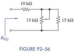
Chapter 2, Problem 2.56P
What is the range of
Expert Solution & Answer
Want to see the full answer?
Check out a sample textbook solution
Students have asked these similar questions
2. For the OPAMP below:
g) Grounding the inputs, perform a DC analysis (assume beta is infinite and VBE=0.7V and neglect the early voltage),calculate the DC currents and voltages everywhere in the circuit (all the collector and emitter currents and voltages aswell as the output voltage). Note that Q4 is 4 times as big as Q9 and Q3h) If Q1 and Q2 have a beta of 100, calculate the input bias current to the opampi) What is the input common mode range of this opamp?j) Calculate the common mode gain if the early voltage of Q3 and Q6 is 50Vk) Calculate the differential gain vo/vid of this circuitI) Calculate the input and output impedance of the opamp assuming beta is 100m) Calculate the input referred offset (Vos) if R2=21K
1. For the difference amplifier below, R1=R3=10K, R2=R4=50k, assume opamp is ideala) Find the differential mode gain, Admb) Find the input impedance (differential, between wi and va)c) Find the common mode gain in the presence of resistor mismatch (If R3=R1+ deltaR1, R4=R2+ deltaR2, deltaR1=100, deltaR2=500)d) Find the common mode rejection ratio (CMRR)e) Find the input impedance and output impedancef) If the OPAMP has an input current of 100uA, find the output offset voltage, set Vi1 = Vi2=0V
For the circuit shown, I-20 mA, R₁ =10000 2, R2 =2000 Q, R3 -2000 Q, R₁-6000 2, Vcc 5 V and the
OPAMP is ideal with regions of operation are considered.
The output current lo in mA is (choose the closet value):
R₂
Is
R₁
W
VCC
-VCC
The relative tolerance for this problem is 1 %.
-0.458
-0.833
6.667
-6.667
○ 0.458
0.833
w
R3
w
RL
Chapter 2 Solutions
ANALYSIS+DESIGN OF LINEAR CIRCUITS(LL)
Ch. 2 - Prob. 2.1PCh. 2 - The voltage across a particular resistor is 8.60 V...Ch. 2 - You can choose to connect either a 4.7-k resistor...Ch. 2 - A model railroader wants to be able to...Ch. 2 - A 100-k resistor dissipates 50mW. Find the current...Ch. 2 - The conductance of a particular semiconductor...Ch. 2 - In Figure P2—7 the resistor dissipates 25 mW. Find...Ch. 2 - In Figure P2—8 find Rx and the power supplied by...Ch. 2 - A resistor found in the lab has three orange...Ch. 2 - The iv characteristic of a nonlinear resistor is...
Ch. 2 - A 100-k resistor has a power rating of 0.25 W....Ch. 2 - A certain type of film resistor is available with...Ch. 2 - Figure P2—13 shows the circuit symbol for a class...Ch. 2 - A thermistor is a temperature-sensing element...Ch. 2 - In Figure P2-15i2=6A and i3=2A. Find i1 and i4.Ch. 2 - In Figure P2-16 determine which elements are in...Ch. 2 - For the circuit in Figure P2—17: Identify the...Ch. 2 - In Figure P2-17 i2=30mA and i4=20mA. Find i1 and...Ch. 2 - For the circuit in Figure P2—19: Identify the...Ch. 2 - In Figure P2-19 v2=20V,v3=20V, and v4=6V. Find...Ch. 2 - In many circuits the ground is often the metal...Ch. 2 - The circuit in figure P2-22 is organized around...Ch. 2 - Are any of the elements in Figure P2-23 in series...Ch. 2 - Are any of the elements in Figure P2-24 in series...Ch. 2 - Use the passive sign convention to assign voltage...Ch. 2 - If a wire is connected between nodes B and C in...Ch. 2 - The KCL equations for a three-node circuit are as...Ch. 2 - For the circuit in Figure P2—28, write a complete...Ch. 2 - For the circuit in Figure P2—29, write a complete...Ch. 2 - Find vx and ix in Figure P2-30. Compare the...Ch. 2 - A modeler wants to light his model building using...Ch. 2 - Find vx and ix in Figure P2-32.Ch. 2 - In Figure P2-33: Assign a voltage and current...Ch. 2 - Find vO in the circuit of Figure P2-34.Ch. 2 - Find the power provided by the source in Figure...Ch. 2 - Figure P2-36 shows a subcircuit connected to the...Ch. 2 - In Figure P2-37 ix=0.33mA. Find the value of R.Ch. 2 - Figure P2—38 shows a resistor with one terminal...Ch. 2 - Find the equivalent resistant REQ in Figure P2-39.Ch. 2 - Find the equivalent R EQ in Figure P2-40.Ch. 2 - Find the equivalent resistance REQ in Figure...Ch. 2 - Equivalent resistance is defined at a particular...Ch. 2 - Find REQ in Figure P2—43 when the switch is open....Ch. 2 - Find REQ between nodes A and B for each of the...Ch. 2 - Show how the circuit in Figure P2—45 could be...Ch. 2 - In Figure P2-46 find the equivalent resistance...Ch. 2 - In Figure P2-47 find the equivalent resistance...Ch. 2 - Select a value of RL in Figure P2-48 so that...Ch. 2 - Using no more than four 1-k resistors, show how...Ch. 2 - Do a source transformation at terminals A and B...Ch. 2 - For each of the circuits in Figure P2-51, find the...Ch. 2 - In Figure P2-52, the iv characteristic of network...Ch. 2 - Select the value of Rx in Figure P2-53 so that...Ch. 2 - Two 10-k potentiometers (a variable resistor whose...Ch. 2 - Select the value of R in Figure P2-55 so that...Ch. 2 - What is the range of REQ in Figure P2-56?Ch. 2 - Find the equivalent resistance between terminals A...Ch. 2 - Use voltage division in Figure P2-58 to find...Ch. 2 - Use voltage division in Figure P2-59 to obtain an...Ch. 2 - Use current division in Figure P2-60 to find...Ch. 2 - Use current division in Figure P2-61 to find an...Ch. 2 - Find ix,iy, and iz in Figure P2-62.Ch. 2 - Find vO in the circuit of Figure P2-63.Ch. 2 - You wish to drive a 1-k load from your car battery...Ch. 2 - Find the range of values of vo in Figure P2-65.Ch. 2 - Use current division in the circuit of Figure...Ch. 2 - Figure P2-67 shows a voltage bridge circuit, that...Ch. 2 - A Ideally, a voltmeter has infinite internal...Ch. 2 - Select values for R1,R2, and R3 in Figure P2-69 so...Ch. 2 - Select a value of Rx in Figure P2-70 so that...Ch. 2 - Select a value of Rx in Figure P2-71 so that...Ch. 2 - Use circuit reduction to find vx and ix in Figure...Ch. 2 - Use circuit reduction to find vx,ix, and px in...Ch. 2 - Use circuit reduction to find vx and ix in Figure...Ch. 2 - Use circuit reduction to find vx,ix, and px in...Ch. 2 - Use circuit reduction to find vx and ix in Figure...Ch. 2 - Use source transformation to find ix in Figure...Ch. 2 - Select a value for Rx so that ix=0A in Figure...Ch. 2 - Use source transformations in Figure P2-79 to...Ch. 2 - The current through RL in figure P2-80 is 100mA....Ch. 2 - Select Rx so that 50 V is across it in Figure...Ch. 2 - The box in the circuit in Figure P2-82 is a...Ch. 2 - A circuit is found to have the following element...Ch. 2 - Consider the circuit of Figure P2-88. Use MATLAB...Ch. 2 - Nonlinear Device Characteristics The circuit in...Ch. 2 - Prob. 2.92IPCh. 2 - Center Tapped Voltage Divider Figure P2-93 shows a...Ch. 2 - Active Transducer Figure P2-95 shows an active...Ch. 2 - Programmable Voltage Divider Figure P2-97 shows a...Ch. 2 - Analog Voltmeter Design Figure P2-98(a) shows a...Ch. 2 - MATLAB Function for Parallel Equivalent Resistors...
Knowledge Booster


Learn more about
Need a deep-dive on the concept behind this application? Look no further. Learn more about this topic, electrical-engineering and related others by exploring similar questions and additional content below.Similar questions
- For the circuit shown, let R₁-4, R2-50, R3-2, R4-77 and Vin-18. Find the current I₁ and voltage Vo as follows: Use op-amp building blocks to determine the voltage Vo1: V01 = Then use Vo1 to find the current 11: 1₁ = Find the voltage Vo: Vo= R1 www Vin R₂ ww V01 R3 The relative tolerance for this problem is 9 %. + R4 www +5°arrow_forwardFor the circuit shown, let Vs1 = 13, Vs2 = 7 R1-10, R2= 50, assume ideal-op-amp, and find • The current Is • The output voltage Vo= VSI A S R₁ ww 1 R₂ www V₁₂ + Varrow_forwardFor the circuit shown, let R₁ =16 Q, R₂ =48 2, R3 = 28 2, R4 =84 02, R5 -2002, R6 -80 2, and V₁ =4 mV. Assume ideal op-amp, find (round your answer to three digits) : Va= (MV) Vb = (MV) (mA) Vout = (MV) R₁ R₂ V₁ + R3 Vb W The relative tolerance for this problem is 7 %. ww R4 24 R5 55 R6 VOUTarrow_forward
- For the circuit shown, find the voltage Vo and current l。. Let R₁=8, R2=1, R3-11 and V₂-3. V S (+1 || w R₂ R1 + R3 Vo The voltage Vo is: The current lo is: The relative tolerance for this problem is 3 %.arrow_forwardFor the circuit shown, find currents 11, 12, 13, and the voltage Vo. Assume ideal op-amp, and let R₁=3, R2-40, Ro=85 and 1-6 The current I₁ is: The current 12 is: The current 13 is: The voltage Vo is: R₂ w R₁ 13 w Roarrow_forwardFor the circuit shown, let v₂ = 9, R₁=86, R2= 15, R3 =7, assume ideal-op-amp, and find • The current l₂ = • Voltage gain, Av= Vo/Vs= • The output voltage vo = A US 1+ 1. R₁ R₂ R3 10 +arrow_forward
- For the op-amp circuit shown, find the voltage Vo, and the current lo. Let R₁=8, R2=58, R3-27 and V₂-101. R1 + R₂ ww + V + The voltage Vo The current lo = = The relative tolerance for this problem is 3 % R3arrow_forwardThe circuit shown in Fig. 14.98 has the impedance Z(s) = 1,000(s+1) (s+1+j50)(s+1 – j50) ' s=j@ Find: (a) the values of R, L, C, and G (b) the element values that will raise the resonant frequency by a factor of 103 by frequency scaling Z(s) Figure 14.98 For Prob. 14.81. R 7arrow_forwardChapter 14, Problem 57. Determine the center frequency and bandwidth of the bandpass filters in Fig. 14.88. 1 F ΙΩ ww V. (+ 1 F 10 V 1 H m (a) (b) ΙΩ ww ΙΩ 1HV Figure 14.88 For Prob. 14.57.arrow_forward
- Chapter 14, Problem 43. Calculate the resonant frequency of each of the circuits in Fig. 14.82. C (a) Figure 14.82 For Prob. 14.43. (b) C Larrow_forwardChapter 14, Problem 69. end Design the filter in Fig. 14.94 to meet the following requirements: (a) It must attenuate a signal at 2 kHz by 3 dB compared with its value at 10 MHz. (b) It must provide a steady-state output of v。 (t) input v, (t)=4sin(2 × 10⁸t) V. = 10 sin(2x 10⁸t+ 180°) V for an Rf ww R ww C 1+ Vs Figure 14.94 For Prob. 14.69.arrow_forwardChapter 14, Problem 15. Construct the Bode magnitude and phase plots for 40(s+1) H(s) (s + 2)(s+10) s=j@arrow_forward
arrow_back_ios
SEE MORE QUESTIONS
arrow_forward_ios
Recommended textbooks for you
 Introductory Circuit Analysis (13th Edition)Electrical EngineeringISBN:9780133923605Author:Robert L. BoylestadPublisher:PEARSON
 Delmar's Standard Textbook Of ElectricityElectrical EngineeringISBN:9781337900348Author:Stephen L. HermanPublisher:Cengage Learning
 Programmable Logic ControllersElectrical EngineeringISBN:9780073373843Author:Frank D. PetruzellaPublisher:McGraw-Hill Education
 Fundamentals of Electric CircuitsElectrical EngineeringISBN:9780078028229Author:Charles K Alexander, Matthew SadikuPublisher:McGraw-Hill Education
 Electric Circuits. (11th Edition)Electrical EngineeringISBN:9780134746968Author:James W. Nilsson, Susan RiedelPublisher:PEARSON
 Engineering ElectromagneticsElectrical EngineeringISBN:9780078028151Author:Hayt, William H. (william Hart), Jr, BUCK, John A.Publisher:Mcgraw-hill Education,
Introductory Circuit Analysis (13th Edition)
Electrical Engineering
ISBN:9780133923605
Author:Robert L. Boylestad
Publisher:PEARSON
Delmar's Standard Textbook Of Electricity
Electrical Engineering
ISBN:9781337900348
Author:Stephen L. Herman
Publisher:Cengage Learning
Programmable Logic Controllers
Electrical Engineering
ISBN:9780073373843
Author:Frank D. Petruzella
Publisher:McGraw-Hill Education
Fundamentals of Electric Circuits
Electrical Engineering
ISBN:9780078028229
Author:Charles K Alexander, Matthew Sadiku
Publisher:McGraw-Hill Education
Electric Circuits. (11th Edition)
Electrical Engineering
ISBN:9780134746968
Author:James W. Nilsson, Susan Riedel
Publisher:PEARSON
Engineering Electromagnetics
Electrical Engineering
ISBN:9780078028151
Author:Hayt, William H. (william Hart), Jr, BUCK, John A.
Publisher:Mcgraw-hill Education,
Kirchhoff's Rules of Electrical Circuits; Author: Flipping Physics;https://www.youtube.com/watch?v=d0O-KUKP4nM;License: Standard YouTube License, CC-BY