
Power System Analysis & Design
6th Edition
ISBN: 9781305636187
Author: Glover, J. Duncan, Overbye, Thomas J. (thomas Jeffrey), Sarma, Mulukutla S.
Publisher: Cengage Learning,
expand_more
expand_more
format_list_bulleted
Concept explainers
Videos
Textbook Question
Chapter 2, Problem 2.50P
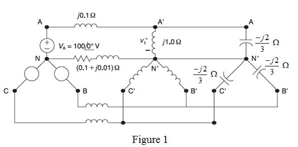
Consider the balanced three-phase system shown in Figure 2.34. Deter mine
Expert Solution & Answer

Trending nowThis is a popular solution!

Students have asked these similar questions
I need help fixing this MATLAB code: as I try to get it working there were some problems:
I need help in construct a matlab code to find the voltage of VR1 to VR4, the currents, and the watts based on that circuit.
Q2: Using D flip-flops, design a synchronous counter. The counter counts in the sequence
1,3,5,7, 1,7,5,3,1,3,5,7,.... when its enable input x is equal to 1; otherwise, the counter
count 0.
Chapter 2 Solutions
Power System Analysis & Design
Ch. 2 - The rms value of v(t)=Vmaxcos(t+) is given by a....Ch. 2 - If the rms phasor of a voltage is given by V=12060...Ch. 2 - If a phasor representation of a current is given...Ch. 2 - Prob. 2.4MCQCh. 2 - Prob. 2.5MCQCh. 2 - Prob. 2.6MCQCh. 2 - Prob. 2.7MCQCh. 2 - Prob. 2.8MCQCh. 2 - Prob. 2.9MCQCh. 2 - The average value of a double-frequency sinusoid,...
Ch. 2 - The power factor for an inductive circuit (R-L...Ch. 2 - The power factor for a capacitive circuit (R-C...Ch. 2 - Prob. 2.13MCQCh. 2 - The instantaneous power absorbed by the load in a...Ch. 2 - Prob. 2.15MCQCh. 2 - With generator conyention, where the current...Ch. 2 - Consider the load convention that is used for the...Ch. 2 - Prob. 2.18MCQCh. 2 - The admittance of the impedance j12 is given by...Ch. 2 - Consider Figure 2.9 of the text, Let the nodal...Ch. 2 - The three-phase source line-to-neutral voltages...Ch. 2 - In a balanced three-phase Y-connected system with...Ch. 2 - In a balanced system, the phasor sum of the...Ch. 2 - Consider a three-phase Y-connected source feeding...Ch. 2 - For a balanced- load supplied by a balanced...Ch. 2 - A balanced -load can be converted to an...Ch. 2 - When working with balanced three-phase circuits,...Ch. 2 - The total instantaneous power delivered by a...Ch. 2 - The total instantaneous power absorbed by a...Ch. 2 - Under balanced operating conditions, consider the...Ch. 2 - One advantage of balanced three-phase systems over...Ch. 2 - While the instantaneous electric power delivered...Ch. 2 - Given the complex numbers A1=630 and A2=4+j5, (a)...Ch. 2 - Convert the following instantaneous currents to...Ch. 2 - The instantaneous voltage across a circuit element...Ch. 2 - For the single-phase circuit shown in Figure...Ch. 2 - A 60Hz, single-phase source with V=27730 volts is...Ch. 2 - (a) Transform v(t)=75cos(377t15) to phasor form....Ch. 2 - Let a 100V sinusoidal source be connected to a...Ch. 2 - Consider the circuit shown in Figure 2.23 in time...Ch. 2 - For the circuit shown in Figure 2.24, compute the...Ch. 2 - For the circuit element of Problem 2.3, calculate...Ch. 2 - Prob. 2.11PCh. 2 - The voltage v(t)=359.3cos(t)volts is applied to a...Ch. 2 - Prob. 2.13PCh. 2 - A single-phase source is applied to a...Ch. 2 - Let a voltage source v(t)=4cos(t+60) be connected...Ch. 2 - A single-phase, 120V(rms),60Hz source supplies...Ch. 2 - Consider a load impedance of Z=jwL connected to a...Ch. 2 - Let a series RLC network be connected to a source...Ch. 2 - Consider a single-phase load with an applied...Ch. 2 - A circuit consists of two impedances, Z1=2030 and...Ch. 2 - An industrial plant consisting primarily of...Ch. 2 - The real power delivered by a source to two...Ch. 2 - A single-phase source has a terminal voltage...Ch. 2 - A source supplies power to the following three...Ch. 2 - Consider the series RLC circuit of Problem 2.7 and...Ch. 2 - A small manufacturing plant is located 2 km down a...Ch. 2 - An industrial load consisting of a bank of...Ch. 2 - Three loads are connected in parallel across a...Ch. 2 - Prob. 2.29PCh. 2 - Figure 2.26 shows three loads connected in...Ch. 2 - Consider two interconnected voltage sources...Ch. 2 - Prob. 2.35PCh. 2 - Prob. 2.36PCh. 2 - Prob. 2.37PCh. 2 - Prob. 2.38PCh. 2 - Prob. 2.39PCh. 2 - A balanced three-phase 240-V source supplies a...Ch. 2 - Prob. 2.41PCh. 2 - A balanced -connected impedance load with (12+j9)...Ch. 2 - A three-phase line, which has an impedance of...Ch. 2 - Two balanced three-phase loads that are connected...Ch. 2 - Two balanced Y-connected loads, one drawing 10 kW...Ch. 2 - Three identical impedances Z=3030 are connected in...Ch. 2 - Two three-phase generators supply a three-phase...Ch. 2 - Prob. 2.48PCh. 2 - Figure 2.33 gives the general -Y transformation....Ch. 2 - Consider the balanced three-phase system shown in...Ch. 2 - A three-phase line with an impedance of...Ch. 2 - A balanced three-phase load is connected to a...Ch. 2 - What is a microgrid?Ch. 2 - What are the benefits of microgrids?Ch. 2 - Prob. CCSQCh. 2 - Prob. DCSQ
Knowledge Booster


Learn more about
Need a deep-dive on the concept behind this application? Look no further. Learn more about this topic, electrical-engineering and related others by exploring similar questions and additional content below.Similar questions
- From the collector characteristic curves and the dc load line given below, determine the following: (a) Maximum collector current for linear operation (b) Base current at the maximum collector current (c) VCE at maximum collector current. lc (mA) 600 ΜΑ 60- 500 με 50- 400 με 40- 300 μ Α 30- Q-point 200 ΜΑ 20- 10- 100 μ Α 0 VCE (V) 1 2 3 4 5 6 7 8 9 10 [6 Paarrow_forwardProcedure:- 1- Connect the cct. shown in fig.(2). a ADDS DS Fig.(2) 2-For resistive load, measure le output voltage by using oscilloscope ;then sketch this wave. 3- Measure the average values ::f VL and IL: 4- Repeat steps 2 & 3 but for RL load. Report:- 1- Calculate the D.C. output vcl age theoretically and compare it with the test value. 2- Calculate the harmonic cont :nts of the load voltage, and explain how filter components may be selected. 3- Compare between the three-phase half & full-wave uncontrolled bridge rectifier. 4- Draw the waveform for the c:t. shown in fig.(2) but after replaced Di and D3 by thyristors with a 30° and a2 = 90° 5- Draw the waveform for the cct. shown in fig.(2) but after replace the 6-diodes by 6- thyristor. 6- Discuss your results. Please solve No. 4 and 5arrow_forwardPlease I want solution by handwrittenarrow_forward
- 8 00 ! Required information Consider the circuit given below. 0/2 points awarded 3 ΚΩ www t=0 6kM Scored R 1.5i Vc 1 μF 10 V If R = 5.00 kQ, determine vao+). The value of va(0) is 1.4545 V.arrow_forwardI want to know what does it look in a breadboard circuit, because I want to created it but I not sure it is build properly, can you give me an illustuation base on this image, it do need to real, something like virutal examplearrow_forwardCharge neutrality Since doped semiconductor remains electroneutral, the concentration of negative charges equals the concentration of positive charges. n+ Na,ionized p+Nd,ionized np = n; 2 2 N-Na N N d d р + 2 2 n = Nd-Na 2 + Na - 2 Na +n₁ 2 71/2 1/2 2 2 +n Concentration of electrons and holes 1. Calculate concentrations of electrons and holes at room temperature in Si and Ge with donor concentration of 1.5x10¹7 cm³ and acceptor concentration of 8x1016 cm-3. 2. Will these concentrations change much with the temperature increase to 100°C?arrow_forward
- Answer the questions on the end of the image pleasearrow_forwardAnswer these two questions on the end of the image, please 1.Calculate intrinsic carrier concentration for Si, Ge and GaAs at temperatures -20°C, 20°C (room temperature) and 120°C 2.Compare the obtained data with n and p shown on previous slide 25arrow_forwardCan you help me achieve the requirements using Arduino? I have encountered some issues with these requirements. Q.2: Suppose you have two push buttons connected to ports (0 & 1) and four LED's connected to ports (6-9). Write a program to flash ON the odd LED's if we press the switch 0 for 4s, flash ON the even LED's if we press the switch 1 for 5s and flash ON all the LED's otherwise for 6s.arrow_forward
- Charge carrier concentration in doped semiconductor: compensation n = Na - Na Na - Na >> ni n-type p = n₁²/n 2 if N₂ >> N₁, n = N₁_ and _p=n² / Na d p = Na-Nd p-type Na-Na >> n₁ d 2 n = n₁₂²/p 2 if N₁ >> N₁, p = N₁ and n = n² / Na a n-type Dopant compensation: Examples d n = Na-N₁ = 4×10¹ cm¯ -3 ++++++ n = 4×1016 cm-³ N=6×1016 cm-3 p=n/n=1020/4×1016 = 2.5×10³ cm p-type -3 p=Na-N₁ =8×10 −6×1016 = 2×10¹6 cm³ n=n²/p=1020/2×101 =5×10³ cm³ N2×1016 cm³ ++++++ N=6x1016 cm-3 N = 8×1016 cm-3 p=2×1016 cm³ The resulting charge carrier concentration in compensated semiconductor approximately equals the difference between the donor and acceptor concentrations. Charge carrier concentration in n-type and p-type semiconductors 1. Calculate concentrations of electrons and holes at room temperature in Si containing 2x1017 cm³ of donors and 8x10¹⁶ -3 cm³ of acceptors. Assume that Na, Nd >> n;. αν 2. Calculate concentrations of electrons and holes at room temperature in Ge containing 2x10¹7 cm³ of…arrow_forwardlonization energy of dopants in semiconductors lonization energy of shallow donors and acceptors can be evaluated using hydrogenic model: lonization energy E Hion and orbital radius a, of hydrogen atom Hydrogen Atom moe4 EHion = 13.6 eV a = 8ε²h² Απερη mee² = 5.2918 x 10⁻¹¹ m lonization energy Eion and orbital radius D,A of donors and acceptors electron m* e4 Eion = ~50 meV 8K² &²h² 4πεερη2 "D,A 1 nm m*e² Orbit of an electron bound to a donor in a semiconductor crystal. Energy levels of donors and acceptors Conduction Band ↓ Ec -Ed Donor Level Donor ionization energy Acceptor ionization energy Acceptor Level Εα Ev Valence Band Ionization energy of selected donors and acceptors in silicon Donors Acceptors Dopant Sb P As B Al In Ionization energy, Ec-Ed or Ea-E, (meV) 39 44 54 45 57 160 Hydrogenic model of donors and acceptors Calculate the ionization energies and orbit radii of donors and acceptors in Si and Ge. Dielectric constant of silicon is k = 11.7. Dielectric constant of…arrow_forwardI need help in construct a method in matlab to find the voltage of VR1 to VR4, rhe current, and the power base on that circuit Nominal or Theortical: E1 = 3V , E2 = 9V, E3 = 1.5V R1 =10Kohm, R2 =2Kohm, R3 =1Kohm, R4 =16Kohmarrow_forward
arrow_back_ios
SEE MORE QUESTIONS
arrow_forward_ios
Recommended textbooks for you
 Power System Analysis and Design (MindTap Course ...Electrical EngineeringISBN:9781305632134Author:J. Duncan Glover, Thomas Overbye, Mulukutla S. SarmaPublisher:Cengage Learning
Power System Analysis and Design (MindTap Course ...
Electrical Engineering
ISBN:9781305632134
Author:J. Duncan Glover, Thomas Overbye, Mulukutla S. Sarma
Publisher:Cengage Learning
Fault Analysis in Power Systems part 1a; Author: GeneralPAC: Power System Tutorials;https://www.youtube.com/watch?v=g8itg4MOjok;License: Standard youtube license