
Electric machinery fundamentals
5th Edition
ISBN: 9780073529547
Author: Chapman, Stephen J.
Publisher: MCGRAW-HILL HIGHER EDUCATION
expand_more
expand_more
format_list_bulleted
Concept explainers
Videos
Textbook Question
Chapter 2, Problem 2.1Q
Is the turns ratio of a transformer the same as the ratio of voltages across the transformer? Why or why not?
Expert Solution & Answer
To determine
Whether a transformer’s turns ratio is same as a transformer’s voltage ratio or not along with reason.
Explanation of Solution
Diagram of ideal transformer is:
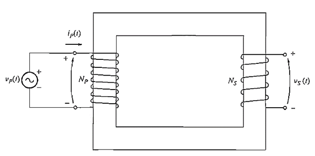
Mutual flux of transformer is
Primary voltage of transformer is
Secondary voltage of transformer is −
Ratio of primary and secondary voltage is
It is observed that ratio of voltages of transformer are same as ratio of their turns because flux linking both the coils is same. So, voltage will be directly proportional to number of turns.
Want to see more full solutions like this?
Subscribe now to access step-by-step solutions to millions of textbook problems written by subject matter experts!
Students have asked these similar questions
12.12 In the circuit of Fig. P12.12(a), is(t) is given by the
waveform shown in Fig. P12.12(b). Determine iL (t) for t≥ 0,
given that R₁ = R₂ = 2 2 and L = 4 H.
is()
R₁
R2:
(a) Circuit
is(t)
8A-
8e-21
elle
(b) is(t)
Figure P12.12 Circuit and waveform for Problem 12.12.
iL
12.12 In the circuit of Fig. P12.12(a), is(t) is given by thewaveform shown in Fig. P12.12(b). Determine iL(t) for t ≥ 0,given that R1 = R2 = 2 W and L = 4 H.
12.4 Determine the Laplace transform of each of the following
functions by applying the properties given in Tables 12-1 and 12-2
on pages 642-643.
(a) fi(t)=4tet u(t)
(b) f2(t)=10cos (12t+60°) u(t)
*(c) f3(t) = 12e−3(t−4) u(t −4)
(d) f4(t) = 30(e³ +e³t) u(t)
(e) fs(t)=16e2t cos 4t u(t)
(f) f6(t)=20te 2 sin 4t u(t)
Chapter 2 Solutions
Electric machinery fundamentals
Ch. 2 - Is the turns ratio of a transformer the same as...Ch. 2 - Why does the magnetization current impose an upper...Ch. 2 - What components compose the excitation current of...Ch. 2 - What is the leakage flux in a transformer? Why is...Ch. 2 - List and describe the types of losses that occur...Ch. 2 - Why does the power factor of a load affect the...Ch. 2 - Why does the short-circuit test essentially show...Ch. 2 - Why does the open-circuit test essentially show...Ch. 2 - How does the per-unit system of measurement...Ch. 2 - Why can autotransformers handle more power than...
Ch. 2 - What are transformer taps? Why are they used?Ch. 2 - What are the problems associated with the Y—Y...Ch. 2 - What is a TCUL transformer?Ch. 2 - How can three-phase transformation be accomplished...Ch. 2 - Prob. 2.15QCh. 2 - Can a 60-Hz transformer be operated on a 50-Hz...Ch. 2 - What happens to a transformer when it is first...Ch. 2 - What is a potential transform? How is it used?Ch. 2 - What is a current transformer? How is it used?Ch. 2 - A distribution transformer is rated at 18 kVA,...Ch. 2 - Why does one hear a hum when standing near a large...Ch. 2 - A 100-kVA, 8000/277-V distribution transformer has...Ch. 2 - A single-phase power system is shown in Figure...Ch. 2 - Consider a simple power system consisting of an...Ch. 2 - The secondary winding of a real transformer has a...Ch. 2 - When travelers from the USA and Canada visit...Ch. 2 - A 1000-VA, 230/115-V transformer has been tested...Ch. 2 - A 30-kVA, 8000/230-V distribution transformer has...Ch. 2 - A 150-MVA, 15/200-kV, single-phase power...Ch. 2 - A 5000-kVA, 230/13.8-kV, single-phase power...Ch. 2 - A three-phase transformer bank is to handle 500...Ch. 2 - A 100-MVA, 230/115-kV, Y three-phase power...Ch. 2 - Three 20-kVA, 24,000/277-V distribution...Ch. 2 - A 14,000/480-V, three-phase, Y-connected...Ch. 2 - A 13.8-kV, single-phase generator supplies power...Ch. 2 - An autotransformer is used to connect a 12.6-kV...Ch. 2 - Prove the following statement: If a transformer...Ch. 2 - A 10-kVA, 480/120-V conventional transformer is to...Ch. 2 - A 10-kVA, 480/120-V conventional transformer is to...Ch. 2 - Two phases of a 14.4-kV, three-phase distribution...Ch. 2 - A 50-kVA, 20,000/480-V, 60-Hz, single-phase...Ch. 2 - Prove that the three-phase system of voltages on...Ch. 2 - Prove that the three-phase system of voltages on...Ch. 2 - A single-phase, 10-kVA, 480/120-V transformer is...Ch. 2 - Figure P2-4 shows a one-line diagram of a power...
Knowledge Booster


Learn more about
Need a deep-dive on the concept behind this application? Look no further. Learn more about this topic, electrical-engineering and related others by exploring similar questions and additional content below.Similar questions
- a) Calculate the values of v and i. + 803 1A Va 82 b) Determine the power dissipated in each resistor. 1A Va (a) + I 50 V 0.2 S (b) + D + 1 Α υ€ 20 Ω 50 V 250 ΩΣ ia (c) (d) Copyright ©2015 Pearson Education, All Rights Reservedarrow_forwardExercise 3-12: Find the Thévenin equivalent of the circuit to the left of terminals (a, b) in Fig. E3.12, and then determine the current I. 502 502 0.6 Ω 20 V | + <302 Ω ΣΙΩ b 2025 Ω 15A Figure E3.12arrow_forward2. Consider following feedback system. r(t) e(t) y(t) K G(s) 1 where G(S) = s²+as+b In above, K, a and b are constants. Select the values of K, a and b in a way so that (i) (ii) (iii) the closed loop system is stable, steady-state error of the closed-loop system for step input is 0.2, the closed-loop response has 20% overshoot and 2 seconds as settling time.arrow_forward
- 4. Answer the following questions. Take help from ChatGPT to answer these questions (if you need). But write the answers briefly using your own words with no more than two sentences, and make sure you check whether ChatGPT is giving you the appropriate answers in the context of class. a) What is the advantage of the PI controller over the proportional controller? b) What is the advantage of the PD controller over a proportional controller? c) In the presence of noise, what problem do we face implementing the derivate part of the PID (or PD) controller? To address this, what do we usually use? d) What are the forms of lead compensator and lag compensator? How do these two types of compensators differ?arrow_forward3. Consider the following closed-loop system as shown in the figure. 16 Ge(s) s(s + 4) Suppose Ge(s) is a PID controller with Kp = 1, KD = 2 and K₁ = 3. a) Find the controller transfer function G₁(s). b) Find the open-loop transfer function. c) Find the closed-loop transfer function.arrow_forwardExercise 3-12: Find the Thévenin equivalent of the circuit to the left of terminals (a, b) in Fig. E3.12, and then determine the current I. 502 5 Ω 0.6 Ω a 3Ω ΣΙΩ b 20 V 1 + 2027 15A Figure E3.12arrow_forward
- solve and show workarrow_forwardDon't use ai to answer I will report you answerarrow_forwardvalues. 4. Discussion: DEPA الأمهريائية RING Compare between theoretic bination effect of Kp and KI at first order and second order systems regarding steady-state errors and transient responses with the practical. In Experiment PI Controllerarrow_forward
- Ⓡ 1. Discuss the relationship between DMA-out and A-out signals. 2. Explain the results of steps 3 and 4 in Experiment 16-2. Unit 16 CVSD System Table 16-2 CVSD demodulator (CLK out - 90KHz) A-in Input Signal DMD-out Waveform & Frequency DMA-out Waveform & Frequency TKHz 1Vpp Sinewave 3KHz 1Vpp Sinewave 200Hz 1Vpp Sinewavearrow_forward3. Describe the function of the lowpass filter (LPF) used in CVSD system.arrow_forwardDon't use ai to answer I will report you answerarrow_forward
arrow_back_ios
SEE MORE QUESTIONS
arrow_forward_ios
Recommended textbooks for you
 Electricity for Refrigeration, Heating, and Air C...Mechanical EngineeringISBN:9781337399128Author:Russell E. SmithPublisher:Cengage Learning
 Power System Analysis and Design (MindTap Course ...Electrical EngineeringISBN:9781305632134Author:J. Duncan Glover, Thomas Overbye, Mulukutla S. SarmaPublisher:Cengage Learning
Electricity for Refrigeration, Heating, and Air C...
Mechanical Engineering
ISBN:9781337399128
Author:Russell E. Smith
Publisher:Cengage Learning
Power System Analysis and Design (MindTap Course ...
Electrical Engineering
ISBN:9781305632134
Author:J. Duncan Glover, Thomas Overbye, Mulukutla S. Sarma
Publisher:Cengage Learning
TRANSFORMERS - What They Are, How They Work, How Electricians Size Them; Author: Electrician U;https://www.youtube.com/watch?v=tXPy4OE7ApE;License: Standard Youtube License