
Concept explainers
Videos
The crude-oil pumping rig shown is driven at 20 rpm. The inside diameter of the well pipe is 2 in., and the diameter of the pump rod is 0.75 in. The length of the pump rod and the length of the column of oil lifted during the stroke are essentially the same, and equal to 6000 ft. During the downward stroke, a valve at the lower end of the pump rod opens to let a quantity of oil into the well pipe, and the column of oil is then lifted to obtain a discharge into the connecting pipeline. Thus, the amount of oil pumped in a given time depends upon the stroke of the lower end of the pump rod. Knowing that the upper end of the rod at D is essentially sinusoidal with a stroke of 45 in. and the specific weight of crude oil is 56.2 lb/ft3, determine (a) the output of the well in ft3/min if the shaft is rigid, (b) the output of the well in ft3/min if the stiffness of the rod is 2210 N/m, the equivalent mass of the oil and shaft is 290 kg, and damping is negligible.
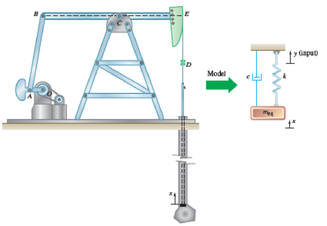
Fig. P19.108
(a)
Find the output of the well
Answer to Problem 19.108P
The output of the well
Explanation of Solution
Given information:
The forced circular frequency
The diameter of the well pipe
The diameter of the pump rod
The stroke of the upper end of the rod
The specific weight of the crude oil
Calculation:
The periodic force frequency is the frequency at which the crude oil is pumped. The speed of the crude oil pump is 20 rpm.
Calculate the periodic force frequency
Here, N is the speed of the pump.
Substitute
The oil flows in the pipe between the pump rod and pipe walls. The diameter of the well pipe is 2 in. and that of the pump rod is 0.75 inch. Thus, the oil flow area is the annular area between the pump rod area and pipe area.
Calculate the oil flow area
Substitute
The system is analogous to the forced vibration system where the vibration is due to simple harmonic motion of the support. The stroke of the lower end of the pump is proportional to the amplitude of the vibration motion.
The expression for the relation between stroke of the pump and the amplitude of vibration as follows:
Here, s is the stroke of the pump and
Calculate the volume of the oil
Substitute
The system is analogous to the forced vibration system where the vibration is due to simple harmonic motion of the support. In the system, the vibration is due to the sinusoidal displacement of the upper end of the rod. The stroke of the sinusoidal motion of the upper end of the rod is 45 inch.
Calculate the magnitude of the static deflection
Substitute
For rigid shaft:
The expression for the amplitude of the forced vibration
Here,
For the rigid shaft, the spring constant is infinite and thus the natural frequency of the rod is infinite. The equation (3) implies that the resulting amplitude of forced vibration, when the natural frequency is infinite, is the amplitude of the forced vibration
Calculate the stroke (s) using the relation:
Substitute
Calculate the volume of the oil
Substitute
The speed of the pump is
Calculate the total volume displaced
Substitute
Therefore, the output of the well
(b)
Find the output of the well
Answer to Problem 19.108P
The output of the well
Explanation of Solution
Given information:
The forced circular frequency
The diameter of the well pipe
The diameter of the pump rod
The stroke of the upper end of the rod
The specific weight of the crude oil
The stiffness of the rod (k) is
The mass of the oil (m) is
Calculation:
Flexible shaft of stiffness:
Calculate the natural circular frequency
Substitute
Calculate the amplitude of forced vibration
Substitute
Calculate the stroke (s) using the relation:
Substitute
Calculate the volume of the oil
Substitute
Calculate the total volume displaced
Substitute
Therefore, the output of the well
Want to see more full solutions like this?
Chapter 19 Solutions
Vector Mechanics for Engineers: Statics and Dynamics


- Can you draw the left view of the first orthographic projectionarrow_forwardImportant: I've posted this question twice and received incorrect answers. I've clearly stated that I don't require AI-generated working out. I need a genuine, expert-written solution with proper working. If you can't provide that, refer this question to someone who can please!. Note: Please provide a clear, step-by-step handwritten solution (no AI involvement). I require an expert-level answer and will assess it based on quality and accuracy with that I'll give it a thumbs up or down!. Hence, refer to the provided image for clarity. Double-check everything for correctness before submitting. Thank you!arrow_forwardNote: Please provide a clear, step-by-step simplified handwritten working out (no explanations!), ensuring it is done without any AI involvement. I require an expert-level answer, and I will assess and rate based on the quality and accuracy of your work and refer to the provided image for more clarity. Make sure to double-check everything for correctness before submitting appreciate your time and effort!. Question:arrow_forward
- Note: Please provide a clear, step-by-step simplified handwritten working out (no explanations!), ensuring it is done without any AI involvement. I require an expert-level answer, and I will assess and rate based on the quality and accuracy of your work and refer to the provided image for more clarity. Make sure to double-check everything for correctness before submitting appreciate your time and effort!. Question: If the flow rate through the system below is 0.04m3s-1, find the difference in elevation H of the two reservoirs.arrow_forwardNote: Please provide a clear, step-by-step simplified handwritten working out (no explanations!), ensuring it is done without any AI involvement. I require an expert-level answer, and I will assess and rate based on the quality and accuracy of your work and refer to the provided image for more clarity. Make sure to double-check everything for correctness before submitting thanks!. Question: (In the image as provided)arrow_forwardNote: Please provide a clear, step-by-step simplified handwritten working out (no explanations!), ensuring it is done without any AI involvement. I require an expert-level answer, and I will assess and rate based on the quality and accuracy of your work and refer to the provided image for more clarity. Make sure to double-check everything for correctness before submitting thanks!. Question: The rectangular gate shown below is 3 m wide. Compute the force P needed to hold the gate in the position shown.arrow_forward
- Note: Please provide a clear, step-by-step simplified handwritten working out (no explanations!), ensuring it is done without any AI involvement. I require an expert-level answer, and I will assess and rate based on the quality and accuracy of your work and refer to the provided image for more clarity. Make sure to double-check everything for correctness before submitting thanks!. Question1: If the following container is 0.6m high, 1.2m wide and half full with water, determine the pressure acting at points A, B, and C if ax=2.6ms^-2.arrow_forwardPlease read the imagearrow_forwardChapter 12 - Lecture Notes.pptx: (MAE 272-01) (SP25) DY... Scoresarrow_forwardConsider a large 6-cm-thick stainless steel plate (k = 15.1 W/m-K) in which heat is generated uniformly at a rate of 5 × 10⁵ W/m³. Both sides of the plate are exposed to an environment at 30°C with a heat transfer coefficient of 60 W/m²K. Determine the value of the highest and lowest temperature. The highest temperature is The lowest temperature is °C. °C.arrow_forwardSketch and explain a PV Diagram and a Temperature Entropy Diagram for a 4 stroke diesel engine please, please explain into detail the difference bewteen the two and referance the a diagram. Please include a sketch or an image of each diagramarrow_forwardDraw left view of the first orthographic projectionarrow_forwardarrow_back_iosSEE MORE QUESTIONSarrow_forward_ios
 Elements Of ElectromagneticsMechanical EngineeringISBN:9780190698614Author:Sadiku, Matthew N. O.Publisher:Oxford University Press
 Mechanics of Materials (10th Edition)Mechanical EngineeringISBN:9780134319650Author:Russell C. HibbelerPublisher:PEARSON
 Thermodynamics: An Engineering ApproachMechanical EngineeringISBN:9781259822674Author:Yunus A. Cengel Dr., Michael A. BolesPublisher:McGraw-Hill Education
 Control Systems EngineeringMechanical EngineeringISBN:9781118170519Author:Norman S. NisePublisher:WILEY
 Mechanics of Materials (MindTap Course List)Mechanical EngineeringISBN:9781337093347Author:Barry J. Goodno, James M. GerePublisher:Cengage Learning
 Engineering Mechanics: StaticsMechanical EngineeringISBN:9781118807330Author:James L. Meriam, L. G. Kraige, J. N. BoltonPublisher:WILEY