
Engineering Mechanics: Statics & Dynamics (14th Edition)
14th Edition
ISBN: 9780133915426
Author: Russell C. Hibbeler
Publisher: PEARSON
expand_more
expand_more
format_list_bulleted
Concept explainers
Videos
Textbook Question
Chapter 19.2, Problem 1PP
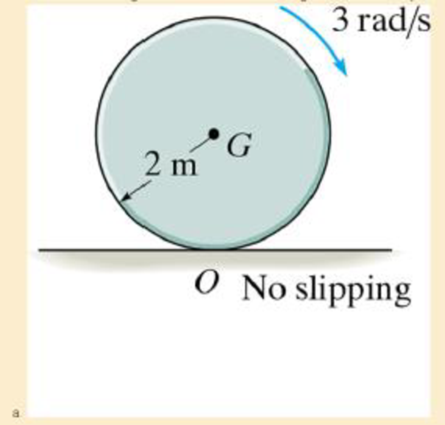
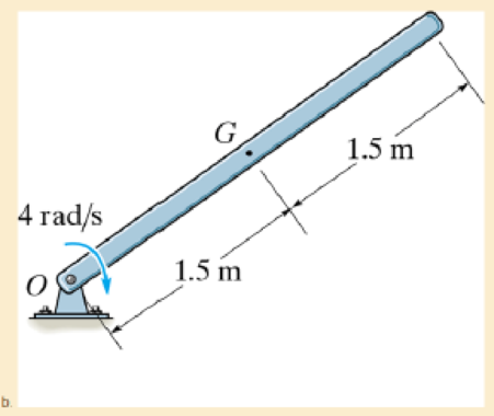
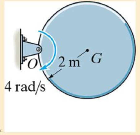
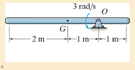
Determine the angular momentum of the 100-kg disk or rod about point G and about point O
Expert Solution & Answer
Want to see the full answer?
Check out a sample textbook solution
Students have asked these similar questions
Draw the free-body diagram for the pinned assembly shown. Find the magnitude of the forces
acting on each member of the assembly.
1500 N
1500 N
C
45°
45°
45°
45°
1000 mm
An elastic bar of length L spins with angular velocity ω about an axis, as shown in the figure below. The radial acceleration at a generic point x along the bar is a(x) = ω 2 x. Due to this radial acceleration, the bar stretches along x with displacement function u(x). The displacement u(x) is governed by the following equations: ( d dx (σ(x)) + ρa(x) = 0 PDE σ(x) = E du dx Hooke’s law (1) where σ(x) is the axial stress in the rod, ρ is the mass density, and E is the (constant) Young’s modulus. The bar is pinned on the rotation axis at x = 0, and it is free at x = L.
Determine:1. Appropriate BCs for this physical problem.2. The displacement function u(x).3. The stress function σ(x).
With reference to the given figure:
a) Draw a free-body diagram of the structure supporting the pulley.
b) Draw shear and bending moment diagrams for both the vertical and horizontal portions
of the structure.
48 in.
100 lb
12 in.
Cable
27 in.
12-in.
pulley radius
100 lb
Cable
Chapter 19 Solutions
Engineering Mechanics: Statics & Dynamics (14th Edition)
Ch. 19.2 - Determine the angular momentum of the 100-kg disk...Ch. 19.2 - Determine the angular impulse about point O for t...Ch. 19.2 - The 60-kg wheel has a radius of gyration about its...Ch. 19.2 - Prob. 2FPCh. 19.2 - Prob. 3FPCh. 19.2 - Gears A and B of mass 10 kg and 50 kg have radii...Ch. 19.2 - The 50-kg spool is subjected to a horizontal force...Ch. 19.2 - Prob. 6FPCh. 19.2 - The rigid body (slab) has a mass m and rotates...Ch. 19.2 - Prob. 2P
Ch. 19.2 - Show that if a slab is rotating about a fixed axis...Ch. 19.2 - The 40-kg disk is rotating at = 100 rad/s. When...Ch. 19.2 - Prob. 5PCh. 19.2 - Prob. 6PCh. 19.2 - The double pulley consists of two wheels which are...Ch. 19.2 - Prob. 8PCh. 19.2 - Prob. 9PCh. 19.2 - The 30-kg gear A has a radius of gyration about...Ch. 19.2 - The pulley has a weight of 10 lb and may be...Ch. 19.2 - Prob. 12PCh. 19.2 - Prob. 13PCh. 19.2 - The rod of length L and mass m lies on a smooth...Ch. 19.2 - Prob. 15PCh. 19.2 - Prob. 16PCh. 19.2 - Prob. 17PCh. 19.2 - The 4-kg slender rod rests on a smooth floor If it...Ch. 19.2 - The double pulley consists of two wheels which are...Ch. 19.2 - The 100-kg spool is resting on the inclined...Ch. 19.2 - Prob. 21PCh. 19.2 - The two gears A and B have weights and radii of...Ch. 19.2 - Prob. 23PCh. 19.2 - The 30-kg gear is subjected to a force of P =...Ch. 19.2 - The 30-lb flywheel A has a radius of gyration...Ch. 19.2 - Prob. 26PCh. 19.2 - Prob. 27PCh. 19.2 - Prob. 28PCh. 19.4 - The turntable T of a record player has a mass of...Ch. 19.4 - The 10-g bullet having a velocity of 800 m/s is...Ch. 19.4 - Prob. 31PCh. 19.4 - Prob. 32PCh. 19.4 - Prob. 33PCh. 19.4 - Prob. 34PCh. 19.4 - The 2-kg rod ACB supports the two 4-kg disks at...Ch. 19.4 - The satellite has a mass of 200 kg and a radius of...Ch. 19.4 - Disk A has a weight of 20 lb. An inextensible...Ch. 19.4 - The plank has a weight of 30 lb, center of gravity...Ch. 19.4 - The 12-kg rod AB is pinned to the 40-kg disk. If...Ch. 19.4 - A thin rod of mass m has an angular velocity o...Ch. 19.4 - Prob. 41PCh. 19.4 - Prob. 42PCh. 19.4 - Prob. 43PCh. 19.4 - Prob. 44PCh. 19.4 - The 10-lb block is sliding on the smooth surface...Ch. 19.4 - Prob. 46PCh. 19.4 - The pendulum consists of a 15-kg solid ball and...Ch. 19.4 - Prob. 48PCh. 19.4 - The 20-kg disk strikes the step Without...Ch. 19.4 - The solid ball of mass m is dropped with a...Ch. 19.4 - Prob. 52PCh. 19.4 - The wheel has a mass of 50 kg and a radius of...Ch. 19.4 - Prob. 54PCh. 19.4 - Prob. 55PCh. 19.4 - Prob. 56PCh. 19.4 - Prob. 57PCh. 19.4 - Prob. 58PCh. 19.4 - The cable is subjected to a force of P = (10t2)...Ch. 19.4 - Prob. 2RPCh. 19.4 - The tire has a mass of 9 kg and a rad1us of...Ch. 19.4 - Prob. 4RPCh. 19.4 - The spool has a weight of 30 lb and a radius of...Ch. 19.4 - Prob. 6RPCh. 19.4 - Prob. 7RPCh. 19.4 - Prob. 8RP
Knowledge Booster


Learn more about
Need a deep-dive on the concept behind this application? Look no further. Learn more about this topic, mechanical-engineering and related others by exploring similar questions and additional content below.Similar questions
- Consider a standard piston engine . Draw a free body diagram of the piston. Then:a) For an A SI engine with a 100 mm bore at an instantaneous cylinder pressure of 42 bar i. Calculate the level of the combustion gas loading force on the wrist pin in kN. b) Repeat this calculationfor a forced-induction Diesel engine with a 145 mm boreat a cylinder pressure of 115 bararrow_forwardA punch press with flywheel adequate to minimize speed fluctuation produces 120 punching strokes per minute, each providing an average force of 2000 N over a stroke of 50 mm. The press is driven through a gear reducer by a shaft rotating 200 rpm. Overall efficiency is 80%. a) What power (W) is transmitted through the shaft? b) What average torque is applied to the shaft?arrow_forward1.58 The crankshaft of a single-cylinder air compressor rotates 1800 rpm. The piston area is 2000 mm2 and the piston stroke is 50 mm. Assume a simple “idealized” case where the average gas pressure acting on the piston during the compression stroke is 1 MPa, and pressure during the intake stroke is negligible. The compressor is 80% efficient. A flywheel provides adequate control of the speed fluctuation. a) What motor power (kW) is required to drive the crankshaft? b) What torque is transmitted through the crankshaft?arrow_forward
- 28. The shaft shown in Figure P5-28 is supported by bear- ings at each end, which have bores of 20.0 mm. Design the shaft to carry the given load if it is steady and the shaft is stationary. Make the dimension a as large as pos- sible while keeping the stress safe. Determine the required d 20 mm 5.4 kN d D = ? Length not to scale -α = = -125 mm 20 mm a = -250 mm- FIGURE P5-28 (Problems 28, 29, and 30)arrow_forwardThe motor shown operates at constant speed and develops a torque of 100 lb-in during normal operation. Attached to the motor shaft is a gear reducer of ratio 5:1, that is, the reducer output shaft rotates in the same direction as the motor but at one-fifth motor speed. Rotation of the reducer housing is prevented by the "torque arm" pin-connected at each end as shown. The reducer output shaft drives the load through a flexible coupling. Neglecting gravity and friction, what loads are applied to (a) the torque arm, (b) the motor output shaft, and (c) the reducer output shaft? Motor Gear reducer Flexible coupling (To load) Torque arm- Torque arm Reducer output shaft Motor Reducer Shaft rotationarrow_forwardPlease can you help with ten attatched question?arrow_forward
- An AISI 1018 steel ball with 1.100-in diameter is used as a roller between a flat plate made from 2024 T3 aluminum and a flat table surface made from ASTM No. 30 gray cast iron. Determine the maximum amount of weight that can be stacked on the aluminum plate without exceeding a maximum shear stress of 19.00 kpsi in any of the three pieces. Assume the figure given below, which is based on a typical Poisson's ratio of 0.3, is applicable to estimate the depth at which the maximum shear stress occurs for these materials. 1.0 0.8 Ratio of stress to Pmax 0.4 90 0.6 στ Tmax 0.2 0.5a a 1.5a 2a 2.5a За Distance from contact surface The maximum amount of weight that can be stacked on the aluminum plate is lbf.arrow_forwardA carbon steel ball with 27.00-mm diameter is pressed together with an aluminum ball with a 36.00-mm diameter by a force of 11.00 N. Determine the maximum shear stress and the depth at which it will occur for the aluminum ball. Assume the figure given below, which is based on a typical Poisson's ratio of 0.3, is applicable to estimate the depth at which the maximum shear stress occurs for these materials. 1.0 0.8 Ratio of stress to Pma 9 0.6 στ 24 0.4 Tmax 0.2 0 0.5a a 1.5a Z 2a 2.5a За Distance from contact surface The maximum shear stress is determined to be MPa. The depth in the aluminum ball at which the maximum shear stress will occur is determined to be [ mm.arrow_forwardShow all work pleasearrow_forward
- Draw top, side, front view With pen(cil) and paper Multi view drawing and handwriting all of itarrow_forwardA wheel of diameter 150.0 mm and width 37.00 mm carrying a load 2.200 kN rolls on a flat rail. Take the wheel material as steel and the rail material as cast iron. Assume the figure given, which is based on a Poisson's ratio of 0.3, is applicable to estimate the depth at which the maximum shear stress occurs for these materials. At this critical depth, calculate the Hertzian stresses σr, σy, σz, and Tmax for the wheel. 1.0 0.8 0, т Ratio of stress to Pmax 0.4 0.6 90 69 0.2 0.5b b 1.5b Tmax 2b Distance from contact surface The Hertizian stresses are as follows: 02 = or = -23.8 psi for the wheel =| necessary.) σy for the wheel =| MPa σz for the wheel = MPa V4 for the wheel = | MPa 2.5b ཡི 3b MPa (Include a minus sign ifarrow_forwardOnly question 3arrow_forward
arrow_back_ios
SEE MORE QUESTIONS
arrow_forward_ios
Recommended textbooks for you
 Elements Of ElectromagneticsMechanical EngineeringISBN:9780190698614Author:Sadiku, Matthew N. O.Publisher:Oxford University Press
 Mechanics of Materials (10th Edition)Mechanical EngineeringISBN:9780134319650Author:Russell C. HibbelerPublisher:PEARSON
 Thermodynamics: An Engineering ApproachMechanical EngineeringISBN:9781259822674Author:Yunus A. Cengel Dr., Michael A. BolesPublisher:McGraw-Hill Education
 Control Systems EngineeringMechanical EngineeringISBN:9781118170519Author:Norman S. NisePublisher:WILEY
 Mechanics of Materials (MindTap Course List)Mechanical EngineeringISBN:9781337093347Author:Barry J. Goodno, James M. GerePublisher:Cengage Learning
 Engineering Mechanics: StaticsMechanical EngineeringISBN:9781118807330Author:James L. Meriam, L. G. Kraige, J. N. BoltonPublisher:WILEY
Elements Of Electromagnetics
Mechanical Engineering
ISBN:9780190698614
Author:Sadiku, Matthew N. O.
Publisher:Oxford University Press
Mechanics of Materials (10th Edition)
Mechanical Engineering
ISBN:9780134319650
Author:Russell C. Hibbeler
Publisher:PEARSON
Thermodynamics: An Engineering Approach
Mechanical Engineering
ISBN:9781259822674
Author:Yunus A. Cengel Dr., Michael A. Boles
Publisher:McGraw-Hill Education
Control Systems Engineering
Mechanical Engineering
ISBN:9781118170519
Author:Norman S. Nise
Publisher:WILEY
Mechanics of Materials (MindTap Course List)
Mechanical Engineering
ISBN:9781337093347
Author:Barry J. Goodno, James M. Gere
Publisher:Cengage Learning
Engineering Mechanics: Statics
Mechanical Engineering
ISBN:9781118807330
Author:James L. Meriam, L. G. Kraige, J. N. Bolton
Publisher:WILEY
Dynamics - Lesson 1: Introduction and Constant Acceleration Equations; Author: Jeff Hanson;https://www.youtube.com/watch?v=7aMiZ3b0Ieg;License: Standard YouTube License, CC-BY