
Applied Statics and Strength of Materials (6th Edition)
6th Edition
ISBN: 9780133840544
Author: George F. Limbrunner, Craig D'Allaird, Leonard Spiegel
Publisher: PEARSON
expand_more
expand_more
format_list_bulleted
Videos
Textbook Question
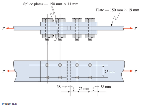
Chapter 19, Problem 19.17SP
Calculate the allowable tensile load for the butt joint shown. The fasteners are 20-mm-diameter A325-N high-strength bolts and the plates are ASTM A36 steel.
Expert Solution & Answer

Trending nowThis is a popular solution!

Students have asked these similar questions
Sketch and explain a PV Diagram and a Temperature Entropy Diagram for a 4 stroke diesel engine
A continuous flow calorimeter was used to obtain the calorific value of a sample of fuel and the following data collected:
Mass of fuel: 2.25 kgInlet water temperature: 11 ° COutlet water temperature 60 ° CQuantity of water: 360 Liters Calorimeter efficiency: 85%Calculate the calorific value of the sample ( kJ / kg ).
Chapter 12 - Lecture Notes.pptx: (MAE 272-01) (SP25) DY...
Scores
Chapter 19 Solutions
Applied Statics and Strength of Materials (6th Edition)
Ch. 19 - Prob. 19.1PCh. 19 - Rework Problem 19.1 assuming a bearing-type...Ch. 19 - Rework Problem 19.1 assuming a bearing-type...Ch. 19 - Compute the allowable tensile load for the...Ch. 19 - Rework Problem 19.4 assuming a bearing-type...Ch. 19 - Rework Problem 19.4 assuming that the bolts are 34...Ch. 19 - Select the number and arrangement of 34 in....Ch. 19 - Calculate the allowable tensile load for the...Ch. 19 - In the connection shown, 14 in. side and end...Ch. 19 - Design the fillet welds parallel to the applied...
Ch. 19 - A fillet weld between two steel plates...Ch. 19 - Design an end connection using longitudinal welds...Ch. 19 - Calculate the allowable tensile load for the butt...Ch. 19 - Calculate the allowable tensile load for the lap...Ch. 19 - Calculate the allowable tensile load for the butt...Ch. 19 - Rework Problem 19.10 assuming that both plates are...Ch. 19 - Rework Problem 19.12 assuming that the angle is an...Ch. 19 - Two ASTM A36 steel plates, each 12 in. by 12 in. ,...Ch. 19 - Rework Problem 19.20 changing the fasteners to 34...Ch. 19 - Calculate the minimum main plate thickness for the...Ch. 19 - A roof truss tension member is made up of 2L6412...Ch. 19 - Rework Problem 19.23 changing the fasteners to six...Ch. 19 - Determine the allowable tensile load that can be...Ch. 19 - The welded connection shown is subjected to an...Ch. 19 - In Problem 19.26, use a 38 in. fillet weld, change...
Knowledge Booster


Learn more about
Need a deep-dive on the concept behind this application? Look no further. Learn more about this topic, mechanical-engineering and related others by exploring similar questions and additional content below.Similar questions
- mylabmastering.pearson.com Chapter 12 - Lecture Notes.pptx: (MAE 272-01) (SP25) DY... P Pearson MyLab and Mastering Scoresarrow_forwardanswer the fallowing Brake Specific Fuel Consumption - 0.3 kg/kwh, Mechanical Efficiency- 90% Calorific Value of Fuel -45 MJ/kg. Given these values, find the indicated power, indicated thermal efficiency and brake thermal efficiencyarrow_forwardProblem 6. The circular plate shown rotates about its vertical diameter. At the instant shown, the angular velocity ₁ of the plate is 10 rad/s and is decreasing at the rate of 25 rad/s². The disk lies in the XY plane and Point D of strap CD moves upward. The relative speed u of Point D of strap CD is 1.5 m/s and is decreasing at the rate of 3 m/s². Determine (a) the velocity of D, (b) the acceleration of D. Answers: =0.75 +1.299]-1.732k m/s a=-28.6 +3.03-10.67k m/s² 200 mm x Zarrow_forwardProblem 1. The flywheel A has an angular velocity o 5 rad/s. Link AB is connected via ball and socket joints to the flywheel at A and a slider at B. Find the angular velocity of link AB and the velocity of slider B at this instant. (Partial Answer: @ABN = -2î + 2.25; red Z -1.2 ft C -7 Y -1.5 ft- B 2.0 ftarrow_forwardNeed help pleasearrow_forwardPROBLEM 15.225 The bent rod shown rotates at the constant rate @₁ = 5 rad/s and collar C moves toward point B at a constant relative speed u = 39 in./s. Knowing that collar C is halfway between points B and D at the instant shown, determine its velocity and acceleration. Answers: v=-45 +36.6)-31.2 k in./s āc = -2911-270} in./s² 6 in 20.8 in. 14.4 in.arrow_forwardNeed help, please show all work, steps, units and please box out and round answers to 3 significant figures. Thank you!..arrow_forwardNeed help, please show all work, steps, units and please box out and round answers to 3 significant figures. Thank you!...arrow_forwardFL y b C Z Determine the moment about O due to the force F shown, the magnitude of the force F = 76.0 lbs. Note: Pay attention to the axis. Values for dimensions on the figure are given in the following table. Note the figure may not be to scale. Variable Value a 1.90 ft b 2.80 ft с 2.60 ft d 2.30 ft Mo 144 ft-lb = -212 × 1 + xk) ☑+212arrow_forward20 in. PROBLEM 15.206 Rod AB is connected by ball-and-socket joints to collar A and to the 16-in.-diameter disk C. Knowing that disk C rotates counterclockwise at the constant rate ₁ =3 rad/s in the zx plane, determine the velocity of collar A for the position shown. 25 in. B 8 in. Answer: -30 in/s =arrow_forwardB Z 001 2.5 ft PROBLEM 15.236 The arm AB of length 16 ft is used to provide an elevated platform for construction workers. In the position shown, arm AB is being raised at the constant rate de/dt = 0.25 rad/s; simultaneously, the unit is being rotated about the Y axis at the constant rate ₁ =0.15 rad/s. Knowing that 20°, determine the velocity and acceleration of Point B. Answers: 1.371 +3.76)+1.88k ft/s a=1.22 -0.342)-0.410k ft/s² Xarrow_forwardF1 3 5 4 P F2 F2 Ꮎ Ꮎ b P 3 4 5 F1 The electric pole is subject to the forces shown. Force F1 245 N and force F2 = 310 N with an angle = 20.2°. Determine the moment about point P of all forces. Take counterclockwise moments to be positive. = Values for dimensions on the figure are given in the following table. Note the figure may not be to scale. Variable Value a 2.50 m b 11.3 m C 13.0 m The moment about point P is 3,414 m. × N- If the moment about point P sums up to be zero. Determine the distance c while all other values remained the same. 1.26 m.arrow_forwardarrow_back_iosSEE MORE QUESTIONSarrow_forward_ios
Recommended textbooks for you
 Welding: Principles and Applications (MindTap Cou...Mechanical EngineeringISBN:9781305494695Author:Larry JeffusPublisher:Cengage Learning
Welding: Principles and Applications (MindTap Cou...
Mechanical Engineering
ISBN:9781305494695
Author:Larry Jeffus
Publisher:Cengage Learning
Differences between Temporary Joining and Permanent Joining.; Author: Academic Gain Tutorials;https://www.youtube.com/watch?v=PTr8QZhgXyg;License: Standard Youtube License