Concept explainers
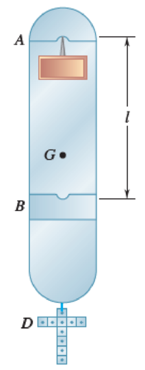
If either a simple or a compound pendulum is used to determine experimentally the acceleration of gravity g, difficulties are encountered. In the case of the simple pendulum, the string is not truly weightless, while in the case of the compound pendulum, the exact location of the mass center is difficult to establish. In the case of a compound pendulum, the difficulty can be eliminated by using a reversible, or Kater, pendulum. Two knife edges A and B are placed so that they are obviously not at the same distance from the mass center G, and the distance l is measured with great precision. The position of a counterweight D is then adjusted so that the period of oscillation τ is the same when either knife edge is used. Show that the period τ obtained is equal to that of a true simple pendulum of length l and that g = (4π2l)/τ2.

Fig. P19.170
Want to see the full answer?
Check out a sample textbook solution
Chapter 19 Solutions
Vector Mechanics for Engineers: Statics and Dynamics
- Auto Controls DONT COPY ANSWERS Perform the partial fraction expansion of the following transfer function and find the impulse response: G(s) = (s/2 + 5/3) / (s^2 + 4s + 6) G(s) =( 6s^2 + 50) / (s+3)(s^2 +4)arrow_forwardDerive the Laplace transform of the following functions. Use the definition of Laplace transform. f(t)=sin4t and f(t)=cos2t Auto Controlsarrow_forwardhelparrow_forward
- any help i dont understandarrow_forwardBattery operated train Mueh Groll CD Af Pair 160,000 kg 0.0005 0.15 19 5m² 1.2kg/m³ 0.98 0.9 Tet neng 0.88 Tesla Prated Tesla Trated Ywheel ng Joyle 2 270 kW 440NM 0,45m 20 8.5kg m Consider a drive cycle of a 500km trip with 3 stops in the middle. Other than the acceleration and deceleration associated with the three stops, the tran maintains. constant cruise speed velocity of 324 km/hr. The tran will fast charge at each stop for 15 min at a rate Peharge = 350 kW Εμ (MN 15MIN Stop w charging (350kW) GMIJ t 6MM 6AW 1) calculate the battery power required to mantain. constant velocity of 324km/hr 2) determine the battery energy, energy required to constant velocity portion of this drive. Cover the 3) calculate the battery energy required to accelerate the train to 324/04/hr. 4) calculate the battery energy that is either fost in deceleration or recovered due to regenerative breaking etcarrow_forwardA 22-lb block B rests as shown on a 28-lb bracket A. The coefficients of friction are μs=0.30μs=0.30 and μk=0.25μk=0.25 between block B and bracket A, and there is no friction in the pulley or between the bracket and the horizontal surface. solved in a previous part. max weight of block C if block B is not to slide on bracket A is 5.045 lbs. Please solve for the acceleration of each Blockarrow_forward
- Test 1 .DOCX * A File Edit View Tools Help INDUSTRIAL ENGINEERING PROGRAMME IMB 411-INDUSTRIAL LOGISTICS TEST 1- SEPTEMBER 12, 2012 Instructions: Answer all questions. Time allowed is 1.5 hours. Identify your script with your student number ONLY (Do not write your name). 1. Define the following terms (i) Logistics management (ii) Supply chain management (iii) Vertical integration in a supply chain (3 Marks) (3 Marks) (3 Marks) 2. (a) Using examples of your choice, briefly discuss the following levels of customer service (1) Pre-transaction elements (ii) Transaction elements (4 Marks) (4 Marks) (iii) Post-transaction elements (4 Marks) (b) "The challenge facing Dumelang Enterprise (Pty) Ltd is to establish the real profitability of their customers and to develop service strategies that will improve the profitability of all customers". As a logistics consultant, briefly discuss how you can advise Dumelang's customer service management. 3. (a) List the three main forms of inventory in a…arrow_forwardIt is decided to install several single-jet Pelton wheels to produce a total power of 18 MW. The available head is 246 m. The wheel rotational speed is 650 rpm and the speed ratio (❤) = 0.46. The diameter of the nozzle (jet) is limited to be 0.167 m with a Cv of 0.95. The efficiency of each turbine is 87%. Determine: (1) The number of Pelton wheels to be used, and (2) The bucket angle.arrow_forwardPlease show All work and fill it in thermodynamicsarrow_forward
- Quick solution required. My request, Don't use Ai. Mechanical engineeringarrow_forwardPlease give handwritten solution, don't use chatgpt. Fbd should be includedarrow_forward(I) [40 Points] Using centered finite difference approximations as done in class, solve the equation for O: d20 dx² + 0.010+ Q=0 subject to the boundary conditions shown in the stencil below. Do this for two values of Q: (a) Q = 0.3, and (b) Q= √(0.5 + 2x)e-sinx (cos(5x)+x-0.5√1.006-x| + e −43*|1+.001+x* | * sin (1.5 − x) + (cosx+0.001 + ex-1250+ sin (1-0.9x)|) * x - 4.68x4. For Case (a) (that is, Q = 0.3), use the stencil in Fig. 1. For Case (b), calculate with both the stencils in Fig. 1 and Fig 2. For all the three cases, show a table as well as a plot of O versus x. Discuss your results. Use MATLAB and hand in the MATLAB codes. 1 0=0 x=0 2 3 4 0=1 x=1 Fig 1 1 2 3 4 5 6 7 8 9 10 11 0=0 x=0 0=1 x=1 Fig 2arrow_forward
 Elements Of ElectromagneticsMechanical EngineeringISBN:9780190698614Author:Sadiku, Matthew N. O.Publisher:Oxford University Press
 Mechanics of Materials (10th Edition)Mechanical EngineeringISBN:9780134319650Author:Russell C. HibbelerPublisher:PEARSON
 Thermodynamics: An Engineering ApproachMechanical EngineeringISBN:9781259822674Author:Yunus A. Cengel Dr., Michael A. BolesPublisher:McGraw-Hill Education
 Control Systems EngineeringMechanical EngineeringISBN:9781118170519Author:Norman S. NisePublisher:WILEY
 Mechanics of Materials (MindTap Course List)Mechanical EngineeringISBN:9781337093347Author:Barry J. Goodno, James M. GerePublisher:Cengage Learning
 Engineering Mechanics: StaticsMechanical EngineeringISBN:9781118807330Author:James L. Meriam, L. G. Kraige, J. N. BoltonPublisher:WILEY


