
Concept explainers
(a)
Find the amplitude of the motion
(a)
Answer to Problem 19.110P
The amplitude of the motion
Explanation of Solution
Given information:
The weight of the bob
The weight of the collar
The length of the simple pendulum (l) is
The amplitude of the collar
The magnitude of static deflection
The frequency
The acceleration due to gravity (g) is
Calculation:
Calculate the mass of the bob
Substitute
Calculate the mass of the collar
Substitute
Calculate the frequency of the period
Substitute
Show the system at before and after moving the collar horizontally as in Figure 1.
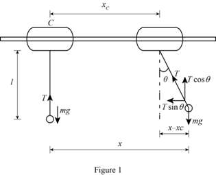
Refer Figure (1),
Before giving horizontal movement, the force mg is equal to the tension in the pendulum.
The expression for the force balance equation for initial condition as follows:
Calculate the value of
The expression for the force balance equation in x-direction in the displaced condition as follows:
Here,
The only force in the x-direction is the tension component
Substitute
Calculate the differential equation of motion using the formula:
Substitute mg for T and
Substitute
Here,
Compare the differential equation (2) with the general differential equation of motion for forced vibration
Calculate the natural circular frequency of vibration
Substitute
Calculate the amplitude of the forced vibration
Substitute
Therefore, the amplitude of the motion
(b)
Find the force that must be applied to collar C (F) to maintain the motion.
(b)
Answer to Problem 19.110P
The force that must be applied to collar C (F) to maintain the motion is
Explanation of Solution
Given information:
The weight of the bob
The weight of the collar
The length of the simple pendulum (l) is
The amplitude of the collar
The magnitude of static deflection
The frequency
The acceleration due to gravity (g) is
Calculation:
Consider the collar as a free body and show the free body diagram equation as in Figure (2).
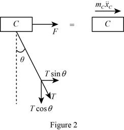
Refer Figure (2), F is the force applied to the collar to maintain the motion is F and
The expression for the force balance equation from Figure 2 as follows:
Substitute mg for T and
Substitute
The expression for the relation for
Differentiate the relation for
Substitute
Substitute
Therefore, the force that must be applied to collar C (F) to maintain the motion is
Want to see more full solutions like this?
Chapter 19 Solutions
Vector Mechanics for Engineers: Statics and Dynamics


- for the values: M1=0.41m, M2=1.8m, M3=0.56m, please account for these in the equations. also please ensure that the final answer is the flow rate in litres per second for each part. please use bernoullis equation where needed if an empirical solutions i srequired. also The solutions should include, but not be limited to, the equations used tosolve the problems, the charts used to solve the problems, detailed working,choice of variables, the control volume considered, justification anddiscussion of results etc.If determining the friction factor, the use of both Moody chart and empiricalequations should be used to verify the validity of the valuearrow_forwardSolve this problem and show all of the workarrow_forwardSolve this problem and show all of the workarrow_forward
- Problem 2: An athlete, starting from rest, pulls handle A to the left with a constant force of P = 150 [N]. Knowing that after the handle A has been pulled 0.5 [m], its velocity is 5 [m/s] to the left, determine: a) A position constraint equation using the given coordinate system. b) An acceleration constraint equation. c) The acceleration of A using kinematics equations. d) The acceleration of B using your constraint equation. e) How much weight (magnitude) the athlete is lifting in pounds using Newton's 2nd Law. You must draw a FBD and KD of the circled assembly, assuming the pulleys are massless. Note: 1 [lbf] = 4.448 [N]. ХА Увarrow_forwardProblem 1: For each of the following images, draw a complete FBD and KD for the specified objects. Then write the equations of motion using variables for all unknowns (e.g., mass, friction coefficient, etc.), plugging in kinematic expressions and simplifying where appropriate. Assume motion in all cases, so any friction would be kinetic. M (a) Blocks A & B (Be careful with acceleration of B relative to accelerating block A) 30° (b) Block A being pulled up my motor M (use rotated rectangular coordinate system) 20° (c) Ball at C, top of swing (use path coordinates) (d) Parasailer/Person (use polar coordinates)arrow_forwardwhere M1=0.41m, M2=1.8m, M3=0.56m, please use bernoulis equation where necessary and The solutions should include, but not be limited to, the equations used tosolve the problems, the charts used to solve the problems, detailed working,choice of variables, the control volume considered, justification anddiscussion of results etc.If determining the friction factor, the use of both Moody chart and empiricalequations should be used to verify the validity of the value.arrow_forward
- Q3. The attachment shown in Fig.2 is made of 1040 HR. Design the weldment (give the pattern, electrode number, type of weld, length of weld, and leg size). All dimensions in mm 120 Fig.2 12 17 b =7.5 5 kN 60 60°arrow_forward15 mm DA 100 mm 50 mm Assuming the load applied P 80 kN. Determine the maximum stress in the bar shown assuming the diameter of the whole A is DA = 25 mm.arrow_forwarduse engineering economic tables, show full solutionarrow_forward
- Do not use chatgpt. I need quick handwritten solution.arrow_forwardSolve this problem and show all of the workarrow_forwardarch Moving to año Question 5 The head-vs-capacity curves for two centrifugal pumps A and B are shown below: Which of the following is a correct statement at a flow rate of 600 ft3/min? Assuming a pump efficiency of 80%. Head [ft] 50 45. 40 CHE 35. 30 25 20 PR 64°F Cloudy 4arrow_forward
 Elements Of ElectromagneticsMechanical EngineeringISBN:9780190698614Author:Sadiku, Matthew N. O.Publisher:Oxford University Press
 Mechanics of Materials (10th Edition)Mechanical EngineeringISBN:9780134319650Author:Russell C. HibbelerPublisher:PEARSON
 Thermodynamics: An Engineering ApproachMechanical EngineeringISBN:9781259822674Author:Yunus A. Cengel Dr., Michael A. BolesPublisher:McGraw-Hill Education
 Control Systems EngineeringMechanical EngineeringISBN:9781118170519Author:Norman S. NisePublisher:WILEY
 Mechanics of Materials (MindTap Course List)Mechanical EngineeringISBN:9781337093347Author:Barry J. Goodno, James M. GerePublisher:Cengage Learning
 Engineering Mechanics: StaticsMechanical EngineeringISBN:9781118807330Author:James L. Meriam, L. G. Kraige, J. N. BoltonPublisher:WILEY