Concept explainers
The

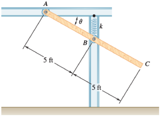
Fig. P17.40 and P17.41
Want to see the full answer?
Check out a sample textbook solution
Chapter 17 Solutions
VECTOR MECHANIC
Additional Engineering Textbook Solutions
Automotive Technology: Principles, Diagnosis, And Service (6th Edition) (halderman Automotive Series)
Starting Out with Programming Logic and Design (5th Edition) (What's New in Computer Science)
SURVEY OF OPERATING SYSTEMS
Fluid Mechanics: Fundamentals and Applications
Problem Solving with C++ (10th Edition)
Mechanics of Materials (10th Edition)
- (b) A steel 'hot rolled structural hollow section' column of length 5.75 m, has the cross-section shown in Figure Q.5(b) and supports a load of 750 kN. During service, it is subjected to axial compression loading where one end of the column is effectively restrained in position and direction (fixed) and the other is effectively held in position but not in direction (pinned). i) Given that the steel has a design strength of 275 MN/m², determine the load factor for the structural member based upon the BS5950 design approach using Datasheet Q.5(b). [11] ii) Determine the axial load that can be supported by the column using the Rankine-Gordon formula, given that the yield strength of the material is 280 MN/m² and the constant *a* is 1/30000. [6] 300 600 2-300 mm wide x 5 mm thick plates. Figure Q.5(b) L=5.75m Pinned Fixedarrow_forwardHelp ارجو مساعدتي في حل هذا السؤالarrow_forwardHelp ارجو مساعدتي في حل هذا السؤالarrow_forward
- Q2: For the following figure, find the reactions of the system. The specific weight of the plate is 500 lb/ft³arrow_forwardQ1: For the following force system, find the moments with respect to axes x, y, and zarrow_forwardQ10) Body A weighs 600 lb contact with smooth surfaces at D and E. Determine the tension in the cord and the forces acting on C on member BD, also calculate the reaction at B and F. Cable 6' 3' wwwarrow_forward
- Help ارجو مساعدتي في حل هذا السؤالarrow_forwardQ3: Find the resultant of the force system.arrow_forwardQuestion 1 A three-blade propeller of a diameter of 2 m has an activity factor AF of 200 and its ratio of static thrust coefficient to static torque coefficient is 10. The propeller's integrated lift coefficient is 0.3.arrow_forward
- (L=6847 mm, q = 5331 N/mm, M = 1408549 N.mm, and El = 8.6 x 10¹⁴ N. mm²) X A ΕΙ B L Y Marrow_forwardCalculate the maximum shear stress Tmax at the selected element within the wall (Fig. Q3) if T = 26.7 KN.m, P = 23.6 MPa, t = 2.2 mm, R = 2 m. The following choices are provided in units of MPa and rounded to three decimal places. Select one: ○ 1.2681.818 O 2. 25745.455 O 3. 17163.636 O 4. 10727.273 ○ 5.5363.636arrow_forwardIf L-719.01 mm, = 7839.63 N/m³, the normal stress σ caused by self-weight at the location of the maximum normal stress in the bar can be calculated as (Please select the correct value of σ given in Pa and rounded to three decimal places.) Select one: ○ 1. 1409.193 2. 845.516 O 3. 11273.545 ○ 4.8455.159 ○ 5.4509.418 6. 2818.386 7.5636.772arrow_forward
 Elements Of ElectromagneticsMechanical EngineeringISBN:9780190698614Author:Sadiku, Matthew N. O.Publisher:Oxford University Press
 Mechanics of Materials (10th Edition)Mechanical EngineeringISBN:9780134319650Author:Russell C. HibbelerPublisher:PEARSON
 Thermodynamics: An Engineering ApproachMechanical EngineeringISBN:9781259822674Author:Yunus A. Cengel Dr., Michael A. BolesPublisher:McGraw-Hill Education
 Control Systems EngineeringMechanical EngineeringISBN:9781118170519Author:Norman S. NisePublisher:WILEY
 Mechanics of Materials (MindTap Course List)Mechanical EngineeringISBN:9781337093347Author:Barry J. Goodno, James M. GerePublisher:Cengage Learning
 Engineering Mechanics: StaticsMechanical EngineeringISBN:9781118807330Author:James L. Meriam, L. G. Kraige, J. N. BoltonPublisher:WILEY


