
Videos
A uniform slender rod of length L is dropped onto rigid supports at A and B. Because support B is slightly lower than support A, the rod strikes A with a velocity
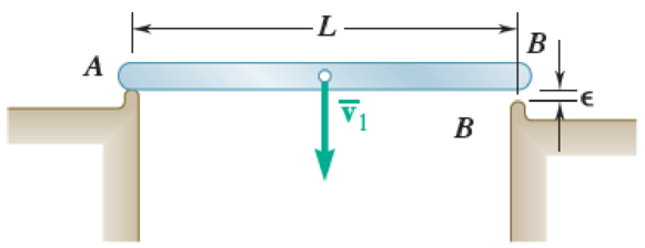
Fig. P17.111
(a)
Find the angular velocity of the rod and the velocity of its mass center immediately after the rod strikes support A.
Answer to Problem 17.111P
The angular velocity of the rod when mass center immediately after the rod strikes support A is
The velocity of the rod when mass center immediately after the rod strikes support A
Explanation of Solution
Given information:
The length of uniform slender rod is L.
The mass of uniform slender rod is m.
The initial velocity of bar before it strikes B is
Calculation:
Write the equation of centroidal moment of inertia
The impact is perfectly elastic at both A and B. Therefore, the coefficient of restitution is one
Write the impact condition for the given system after the rod strikes support A.
Here,
Write the equation of velocity of rod
Here,
Substitute
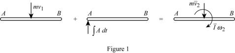
Consider the impulse and momentum principle.
Sketch the impulse and momentum diagram for the first impact at A of the bar as shown in Figure (1).
Here,
Refer Figure (1).
Take moment about A (positive sign in clockwise direction).
Substitute
Simplify the Equation:
Thus, the angular velocity of the rod and the velocity of its mass center immediately after the rod strikes support A is
Find the velocity of the rod when mass center immediately after the rod strikes support A using Equation (1).
Substitute
Thus, the velocity of the rod when mass center immediately after the rod strikes support A
(b)
Find the angular velocity of the rod and the velocity of its mass center immediately after the rod strikes support B.
Answer to Problem 17.111P
The angular velocity of the rod when mass center immediately after the rod strikes support B is
The velocity of the rod when mass center immediately after the rod strikes support B is
Explanation of Solution
Calculation:
Write the impact condition for the given system after the rod strikes support B.
Here,
Write the equation of velocity of rod
Here,
Substitute
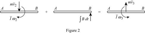
Consider the impulse and momentum principle.
Sketch the impulse and momentum diagram for impact at B of the bar as shown in Figure (2).
Here,
Refer Figure (2).
Take moment about B (positive sign in clockwise direction).
Substitute
Thus, the angular velocity of the rod when mass center immediately after the rod strikes support B is
Find the velocity of the rod when mass center immediately after the rod strikes support B using Equation (2).
Substitute
Thus, the velocity of the rod when mass center immediately after the rod strikes support B
(c)
Find the angular velocity of the rod and the velocity of its mass center immediately after the rod strikes support A again.
Answer to Problem 17.111P
The angular velocity of the rod when mass center immediately after the rod strikes support A again is
The velocity of the rod when mass center immediately after the rod strikes support A again is
Explanation of Solution
Calculation:
Write the impact condition for the given system after the rod again strikes support A.
Here,
Write the equation of velocity of rod
Here,
Substitute
Consider the impulse and momentum principle.
Sketch the impulse and momentum diagram for second impact at A of the bar as shown in Figure (3).
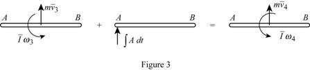
Refer Figure (3).
Take moment about A (positive sign in clockwise direction).
Substitute
Thus, the angular velocity of the uniform slender rod after rod again strikes support A support B is
Find the velocity of rod at its mass center after the rod again strikes support A using Equation (3).
Substitute 0 for
Thus, the velocity of rod at its mass center after the rod again strikes support A is
Want to see more full solutions like this?
Chapter 17 Solutions
VECTOR MECHANIC
Additional Engineering Textbook Solutions
Mechanics of Materials (10th Edition)
Web Development and Design Foundations with HTML5 (8th Edition)
Automotive Technology: Principles, Diagnosis, And Service (6th Edition) (halderman Automotive Series)
Java: An Introduction to Problem Solving and Programming (8th Edition)
Thermodynamics: An Engineering Approach
Elementary Surveying: An Introduction To Geomatics (15th Edition)


- = The frame shown is fitted with three 50 cm diameter frictionless pulleys. A force of F = 630 N is applied to the rope at an angle ◊ 43°. Member ABCD is attached to the wall by a fixed support at A. Find the forces indicated below. Note: The rope is tangent to the pully (D) and not secured at the 3 o'clock position. a b •C *су G E e d BY NC SA 2013 Michael Swanbom Values for dimensions on the figure are given in the following table. Note the figure may not be to scale. Variable Value a 81 cm b 50 cm с 59 cm d 155 cm For all answers, take x as positive to the right and positive upward. At point A, the fixed support exerts a force of: A = + ĴN and a reaction couple of: →> ΜΑ Member CG is in Select an answer magnitude У as k N-m. and carries a force of N.arrow_forwardThe lower jaw AB [Purple 1] and the upper jaw-handle AD [Yellow 2] exert vertical clamping forces on the object at R. The hand squeezes the upper jaw-handle AD [2] and the lower handle BC [Orane 4] with forces F. (Member CD [Red 3] acts as if it is pinned at D, but, in a real vise-grips, its position is actually adjustable.) The clamping force, R, depends on the geometry and on the squeezing force F applied to the handles. Determine the proportionality between the clamping force, R, and the squeezing force F for the dimensions given. d3 d4 R 1 B d1 2 d2 D... d5 F 4 F Values for dimensions on the figure are given in the following table. Note the figure may not be to scale. Variable Value d1 65 mm d2 156 mm d3 50 mm 45 d4 d5 113 mm 30 mm R = Farrow_forwardA triangular distributed load of max intensity w =460 N/m acts on beam AB. The beam is supported by a pin at A and member CD, which is connected by pins at C and D respectively. Determine the reaction forces at A and C. Enter your answers in Cartesian components. Assume the masses of both beam AB and member CD are negligible. cc 040 BY NC SA 2016 Eric Davishahl W A C D -a- B Ул -b- x Values for dimensions on the figure are given in the following table. Note the figure may not be to scale. Variable Value α 5.4 m b 8.64 m C 3.24 m The reaction at A is A = i+ ĴN. λ = i+ Ĵ N. The reaction at C is C =arrow_forward
- 56 Clamps like the one shown are commonly used in woodworking applications. This clamp has the dimensions given in the table below the figure, and its jaws are mm thick (in the direction perpendicular to the plane of the picture). a.) The screws of the clamp are adjusted so that there is a uniform pressure of P = 150 kPa being applied to the workpieces by the jaws. Determine the force carried in each screw. Hint: the uniform pressure can be modeled in 2-D as a uniform distributed load with intensity w = Pt (units of N/m) acting over the length of contact between the jaw and the workpiece. b.) Determine the minimum vertical force (parallel to the jaws) required to pull either one of the workpieces out of the clamp jaws. Use a coefficient of static friction between all contacting surfaces of μs = 0.56 and the same clamping pressure given for part (a). 2013 Michael Swanbom A B C a Values for dimensions on the figure are given in the following table. Note the figure may not be to scale.…arrow_forwardDetermine the force in each member of the space truss given F=5 kN. Use positive to indicate tension and negative to indicate compression. F E Z -2 m. B 3 m C 5 m 3 m A -4 m. AB = KN FAC = FAD = KN KN KN FBC = KN FBD FBE = = KN Farrow_forwardA short brass cyclinder (denisty=8530 kg/m^3, cp=0.389 kJ/kgK, k=110 W/mK, and alpha=3.39*10^-5 m^2/s) of diameter 4 cm and height 20 cm is initially at uniform temperature of 150 degrees C. The cylinder is now placed in atmospheric air at 20 degrees C, where heat transfer takes place by convection with a heat transfer coefficent of 40 W/m^2K. Calculate (a) the center temp of the cylinder, (b) the center temp of the top surface of the cylinder, and (c) the total heat transfer from the cylinder 15 min after the start of the cooling. Solve this problem using the analytical one term approximation method. (Answer: (a) 45.7C, (b)45.3C, (c)87.2 kJ)arrow_forward
- A short brass cyclinder (denisty=8530 kg/m^3, cp=0.389 kJ/kgK, k=110 W/mK, and alpha=3.39*10^-5 m^2/s) of diameter 4 cm and height 20 cm is initially at uniform temperature of 150 degrees C. The cylinder is now placed in atmospheric air at 20 degrees C, where heat transfer takes place by convection with a heat transfer coefficent of 40 W/m^2K. Calculate (a) the center temp of the cylinder, (b) the center temp of the top surface of the cylinder, and (c) the total heat transfer from the cylinder 15 min after the start of the cooling. Solve this problem using the analytical one term approximation method.arrow_forwardA 6 cm high rectangular ice block (k=2.22 W/mK, and alpha=0.124*10^-7 m^2/s) initially at -18 degrees C is placed on a table on its square base 4 cm by 4cm in size in a room at 18 degrees C. The heat transfer coefficent on the exposed surfaces of the ice block is 12 W/m^2K. Disregarding any heat transfer from the base to the table, determine how long it will be before the ice block starts melting. Where on the ice block will the first liquid droplets appear? Solve this problem using the analytical one-term approximation method.arrow_forwardConsider a piece of steel undergoing a decarburization process at 925 degrees C. the mass diffusivity of carbon in steel at 925 degrees C is 1*10^-7 cm^2/s. Determine the depth below the surface of the steel at which the concentration of carbon is reduced to 40 percent from its initial value as a result of the decarburization process for (a) an hour and (b) 10 hours. Assume the concnetration of carbon at the surface is zero throughout the decarburization process.arrow_forward
- Please do not rely too much on chatgpt, because its answer may be wrong. Please consider it carefully and give your own answer. You can borrow ideas from gpt, but please do not believe its answer.Very very grateful! Please do not copy other's work,i will be very very grateful!!arrow_forwardMultiple Choice Circle the best answer to each statement. 1. Which geometry attribute deviation(s) can be limited with a profile of a surface tolerance? A. Location B. Orientation C. Form D. All of the above 2. A true profile may be defined with: A. Basic radii B. Basic angles C. Formulas D. All of the above 3. Which modifier may be applied to the profile tolerance value? A B C. D. All of the above 4. The default tolerance zone for a profile tolerance is: A. Non-uniform B. Unilateral C. Bilateral equal distribution D. Bilateral-unequal distribution 5. An advantage of using a profile tolerance in place of a coordinate tolerance is: A. A bonus tolerance is permitted. B. A datum feature sequence may be specified C. A profile tolerance always controls size D. All of the above 6. The shape of the tolerance zone for a profile tolerance is: A. Two parallel planes B. The same as the true profile of the toleranced surface C. Equal bilateral D. Cylindrical when the diameter symbol is speci- fied…arrow_forwardOne thousand kg/h of a (50-50 wt%) acetone-in-water solution is to be extracted at 25C in a continuous, countercurrent system with pure 1,1,2-trichloroethane to obtain a raffinate containing 10 wt% acetone. Using the following equilibrium data, determine with an equilateral-triangle diagram: a- the minimum flow rate of solvent; b- the number of stages required for a solvent rate equal to 1.5 times minimum, and composition of each streamleaving each stage. c- Repeat the calculation of (a) and (b) if the solvent used has purity 93wt% (4wr% acetone, 3wt% water impurities) acetone water 1,1,2-trichloroethane Raffinate. Weight Extract. Weight 0.6 0.13 0.27 Fraction Acetone Fraction Acetone 0.5 0.04 0.46 0.44 0.56 0.4 0.03 0.57 0.29 0.40 0.3 0.02 0.68 0.12 0.18 0.2 0.015 0.785 0.0 0.0 0.1 0.01 0.89 0.55 0.35 0.1 0.5 0.43 0.07 0.4 0.57 0.03 0.3 0.68 0.02 0.2 0.79 0.01 0.1 0.895 0.005arrow_forward
 Elements Of ElectromagneticsMechanical EngineeringISBN:9780190698614Author:Sadiku, Matthew N. O.Publisher:Oxford University Press
 Mechanics of Materials (10th Edition)Mechanical EngineeringISBN:9780134319650Author:Russell C. HibbelerPublisher:PEARSON
 Thermodynamics: An Engineering ApproachMechanical EngineeringISBN:9781259822674Author:Yunus A. Cengel Dr., Michael A. BolesPublisher:McGraw-Hill Education
 Control Systems EngineeringMechanical EngineeringISBN:9781118170519Author:Norman S. NisePublisher:WILEY
 Mechanics of Materials (MindTap Course List)Mechanical EngineeringISBN:9781337093347Author:Barry J. Goodno, James M. GerePublisher:Cengage Learning
 Engineering Mechanics: StaticsMechanical EngineeringISBN:9781118807330Author:James L. Meriam, L. G. Kraige, J. N. BoltonPublisher:WILEY