
VECTOR MECH. FOR EGR: STATS & DYNAM (LL
12th Edition
ISBN: 9781260663778
Author: BEER
Publisher: MCG
expand_more
expand_more
format_list_bulleted
Concept explainers
Videos
Textbook Question
Chapter 17.1, Problem 17.18P
A slender 9-lb rod can rotate in a vertical plane about a pivot at B. A spring of constant k = 30 lb/ft and of unstretched length 6 in. is attached to the rod as shown. Knowing that the rod is released from rest in the position shown, determine its angular velocity after it has rotated through 90°.
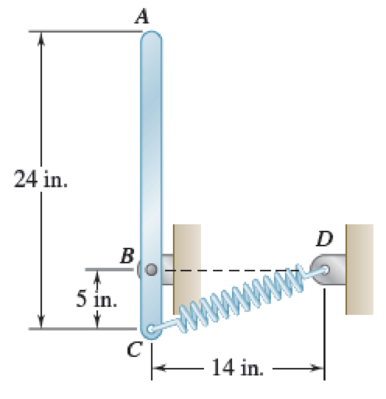
Fig. P17.18
Expert Solution & Answer
Want to see the full answer?
Check out a sample textbook solution
Students have asked these similar questions
Part 1
The storage tank contains lubricating oil of specific gravity 0.86 In one inclined side of the tank,
there is a 0.48 m diameter circular inspection door, mounted on a horizontal shaft along the centre
line of the gate. The oil level in the tank rests 8.8 m above the mounted shaft. (Please refer table
01 for relevant SG, D and h values).
Describe the hydrostatic force and centre of pressure with the aid of a free body diagram of the
inspection door.
Calculate the magnitude of the hydrostatic force and locate the centre
of pressure.
45°
Estimate the moment that would have to be applied to the shaft to
open the gate.
Stop
B
If the oil level raised by 2 m from the current level, calculate the new
moment required to open the gate.
Figure 01
From thermodynamics
please fill in the table show all work step by step
The 150-lb skater passes point A with a speed of 6 ft/s.
(Figure 1)
Determine his speed when he reaches point B. Neglect friction.
Determine the normal force exerted on him by the track at this point.
25 ft
B
= 4x
A
20 ft
x
Chapter 17 Solutions
VECTOR MECH. FOR EGR: STATS & DYNAM (LL
Ch. 17.1 - A round object of mass m and radius r is released...Ch. 17.1 - Prob. 17.2CQCh. 17.1 - Prob. 17.3CQCh. 17.1 - Prob. 17.4CQCh. 17.1 - Slender bar A is rigidly connected to a massless...Ch. 17.1 - A 200-kg flywheel is at rest when a constant 300...Ch. 17.1 - The rotor of an electric motor has an angular...Ch. 17.1 - Prob. 17.3PCh. 17.1 - Two disks of the same material are attached to a...Ch. 17.1 - The flywheel of a punching machine has a weight of...
Ch. 17.1 - Prob. 17.6PCh. 17.1 - Prob. 17.7PCh. 17.1 - Prob. 17.8PCh. 17.1 - The 10-in.-radius brake drum is attached to a...Ch. 17.1 - Prob. 17.10PCh. 17.1 - Each of the gears A and B has a mass of 10 kg and...Ch. 17.1 - Solve Prob. 17.11, assuming that the 6 Nm couple...Ch. 17.1 - Prob. 17.13PCh. 17.1 - The double pulley shown has a mass of 15 kg and a...Ch. 17.1 - Gear A has a mass of 1 kg and a radius of gyration...Ch. 17.1 - A slender rod of length l and mass m is pivoted...Ch. 17.1 - The 15-kg rear hatch of a vehicle opens as shown...Ch. 17.1 - A slender 9-lb rod can rotate in a vertical plane...Ch. 17.1 - An adapted golf device attaches to a wheelchair to...Ch. 17.1 - A 10-kg storm window measuring 900 1500 mm is...Ch. 17.1 - A collar with a mass of 1 kg is rigidly attached...Ch. 17.1 - A collar with a mass of 1 kg is rigidly attached...Ch. 17.1 - Two identical slender rods AB and BC are welded...Ch. 17.1 - Prob. 17.24PCh. 17.1 - A 100-kg solid cylindrical disk, 800 mm in...Ch. 17.1 - Prob. 17.26PCh. 17.1 - Greek engineers had the unenviable task of moving...Ch. 17.1 - A small sphere of mass m and radius r is released...Ch. 17.1 - Prob. 17.29PCh. 17.1 - A half-cylinder with mass m and radius r is...Ch. 17.1 - Prob. 17.31PCh. 17.1 - Two uniform cylinders, each of weight W = 14 lb...Ch. 17.1 - Prob. 17.33PCh. 17.1 - A bar of mass m = 5 kg is held as shown between...Ch. 17.1 - The 1.5-kg uniform slender bar AB is connected to...Ch. 17.1 - The motion of the uniform rod AB is guided by...Ch. 17.1 - Prob. 17.37PCh. 17.1 - Prob. 17.38PCh. 17.1 - The ends of a 9-lb rod AB are constrained to move...Ch. 17.1 - The mechanism shown is one of two identical...Ch. 17.1 - The mechanism shown is one of two identical...Ch. 17.1 - Each of the two rods shown is of length L = 1 m...Ch. 17.1 - The 4-kg rod AB is attached to a collar of...Ch. 17.1 - If in Prob. 17.43 the angular velocity of the...Ch. 17.1 - The uniform rods AB and BC are of mass 3 kg and 8...Ch. 17.1 - The uniform rods AB and BC weigh 2.4 kg and 4 kg,...Ch. 17.1 - The 80-mm-radius gear shown has a mass of 5 kg and...Ch. 17.1 - Prob. 17.48PCh. 17.1 - Three shafts and four gears are used to form a...Ch. 17.1 - The experimental setup shown is used to measure...Ch. 17.1 - Prob. 17.51PCh. 17.2 - The 350-kg flywheel of a small hoisting engine has...Ch. 17.2 - Prob. 17.2IMDCh. 17.2 - Prob. 17.3IMDCh. 17.2 - Prob. 17.52PCh. 17.2 - A bolt located 2 in. from the center of an...Ch. 17.2 - A small grinding wheel is attached to the shaft of...Ch. 17.2 - A uniform 144-lb cube is attached to a uniform...Ch. 17.2 - Prob. 17.56PCh. 17.2 - Prob. 17.57PCh. 17.2 - Prob. 17.58PCh. 17.2 - Prob. 17.59PCh. 17.2 - Each of the double pulleys shown has a centroidal...Ch. 17.2 - Each of the gears A and B has a mass of 675 g and...Ch. 17.2 - Two identical uniform cylinders of mass m and...Ch. 17.2 - Two identical 16-lb uniform cylinders of radius r...Ch. 17.2 - Prob. 17.64PCh. 17.2 - Prob. 17.65PCh. 17.2 - Show that, when a rigid body rotates about a fixed...Ch. 17.2 - Prob. 17.68PCh. 17.2 - A flywheel is rigidly attached to a 1.5-in.-radius...Ch. 17.2 - A wheel of radius r and centroidal radius of...Ch. 17.2 - Prob. 17.71PCh. 17.2 - 17.72 and 17.73The 3-lb carriage C is supported as...Ch. 17.2 - Prob. 17.73PCh. 17.2 - Two uniform cylinders, each of mass m = 6 kg and...Ch. 17.2 - Prob. 17.75PCh. 17.2 - Prob. 17.76PCh. 17.2 - A sphere of radius r and mass m is projected along...Ch. 17.2 - A bowler projects an 8.5-in.-diameter ball...Ch. 17.2 - Prob. 17.79PCh. 17.2 - A satellite has a total weight (on Earth) of 250...Ch. 17.2 - Two 10-lb disks and a small motor are mounted on a...Ch. 17.2 - Prob. 17.82PCh. 17.2 - Prob. 17.83PCh. 17.2 - Prob. 17.84PCh. 17.2 - Prob. 17.85PCh. 17.2 - Prob. 17.86PCh. 17.2 - The 30-kg uniform disk A and the bar BC are at...Ch. 17.2 - Prob. 17.88PCh. 17.2 - A 1.8-kg collar A and a 0.7-kg collar B can slide...Ch. 17.2 - Prob. 17.90PCh. 17.2 - A small 4-lb collar C can slide freely on a thin...Ch. 17.2 - Rod AB has a weight of 6 lb and is attached to a...Ch. 17.2 - A 3-kg uniform cylinder A can roll without sliding...Ch. 17.2 - The 4-kg cylinder B and the 3-kg wedge A are at...Ch. 17.2 - The 6-lb steel cylinder A of radius r and the...Ch. 17.3 - A uniform slender rod AB of mass m is at rest on a...Ch. 17.3 - Prob. 17.5IMDCh. 17.3 - Prob. 17.6IMDCh. 17.3 - At what height h above its center G should a...Ch. 17.3 - A bullet weighing 0.08 lb is fired with a...Ch. 17.3 - In Prob. 17.97, determine (a) the required...Ch. 17.3 - A 16-lb wooden panel is suspended from a pin...Ch. 17.3 - Prob. 17.100PCh. 17.3 - A 45-g bullet is fired with a velocity of 400 m/s...Ch. 17.3 - A 45-g bullet is fired with a velocity of 400 m/s...Ch. 17.3 - The tire shown has a radius R = 300 mm and a...Ch. 17.3 - Prob. 17.104PCh. 17.3 - A uniform slender rod AB of mass m is at rest on a...Ch. 17.3 - A uniform slender rod AB is at rest on a...Ch. 17.3 - A bullet of mass m is fired with a horizontal...Ch. 17.3 - Determine the height h at which the bullet of...Ch. 17.3 - A uniform slender bar of length L = 200 mm and...Ch. 17.3 - A uniform slender rod of length L is dropped onto...Ch. 17.3 - A uniform slender rod AB has a mass m, a length L,...Ch. 17.3 - You have been hired to design a baseball catcher...Ch. 17.3 - The trapeze/lanyard air drop (t/LAD) launch is a...Ch. 17.3 - The uniform rectangular block shown is moving...Ch. 17.3 - The 40-kg gymnast drops from her maximum height of...Ch. 17.3 - A uniform slender rod AB of length L = 600 mm is...Ch. 17.3 - Prob. 17.118PCh. 17.3 - A 1-oz bullet is fired with a horizontal velocity...Ch. 17.3 - For the beam of Prob. 17.119, determine the...Ch. 17.3 - Prob. 17.121PCh. 17.3 - Prob. 17.122PCh. 17.3 - A slender rod AB is released from rest in the...Ch. 17.3 - Prob. 17.124PCh. 17.3 - Block A has a mass m and is attached to a cord...Ch. 17.3 - Prob. 17.126PCh. 17.3 - 17.127 and 17.128Member ABC has a mass of 2.4 kg...Ch. 17.3 - 17.127 and 17.128Member ABC has a mass of 2.4 kg...Ch. 17.3 - Prob. 17.129PCh. 17.3 - Prob. 17.130PCh. 17.3 - A small rubber ball of radius r is thrown against...Ch. 17.3 - Sphere A of mass m and radius r rolls without...Ch. 17.3 - In a game of pool, ball A is rolling without...Ch. 17 - A uniform disk, initially at rest and of constant...Ch. 17 - The 8-in.-radius brake drum is attached to a...Ch. 17 - A uniform slender rod is placed at corner B and is...Ch. 17 - The motion of the slender 250-mm rod AB is guided...Ch. 17 - A baseball attachment that helps people with...Ch. 17 - Disks A and B are made of the same material, are...Ch. 17 - Disks A and B are made of the same material, are...
Additional Engineering Textbook Solutions
Find more solutions based on key concepts
Write a summary list of the problem-solving steps identified in the chapter, using your own words.
BASIC BIOMECHANICS
1.2 Explain the difference between geodetic and plane
surveys,
Elementary Surveying: An Introduction To Geomatics (15th Edition)
Consider the adage Never ask a question for which you do not want the answer. a. Is following that adage ethica...
Experiencing MIS
The solid steel shaft AC has a diameter of 25 mm and is supported by smooth bearings at D and E. It is coupled ...
Mechanics of Materials (10th Edition)
How does a computers main memory differ from its auxiliary memory?
Java: An Introduction to Problem Solving and Programming (8th Edition)
How is the hydrodynamic entry length defined for flow in a pipe? Is the entry length longer in laminar or turbu...
Fluid Mechanics: Fundamentals and Applications
Knowledge Booster


Learn more about
Need a deep-dive on the concept behind this application? Look no further. Learn more about this topic, mechanical-engineering and related others by exploring similar questions and additional content below.Similar questions
- A virtual experiment is designed to determine the effect of friction on the timing and speed of packages being delivered to a conveyor belt and the normal force applied to the tube. A package is held and then let go at the edge of a circular shaped tube of radius R = 5m. The particle at the bottom will transfer to the conveyor belt, as shown below. Run the simulations for μ = 0, 0.1, 0.2, 0.3, 0.4, 0.5, 0.6 and determine the time and speed at which the package is delivered to the conveyor belt. In addition, determine the maximum normal force and its location along the path as measured by angle 0. Submit in hardcopy form: (0) Free Body Diagram, equations underneath, derivations (a) Your MATLAB mfile (b) A table listing the values in 5 columns: μ, T (time of transfer), V (speed of transfer), 0 (angle of max N), Nmax (max N) (c) Based on your results, explain in one sentence what you think will happen to the package if the friction is increased even further, e.g. μ = 0.8. NOTE: The ODE is…arrow_forwardPatm = 1 bar Piston m = 50 kg 5 g of Air T₁ = 600 K P₁ = 3 bar Stops A 9.75 x 10⁻³ m² FIGURE P3.88arrow_forwardAssume a Space Launch System (Figure 1(a)) that is approximated as a cantilever undamped single degree of freedom (SDOF) system with a mass at its free end (Figure 1(b)). The cantilever is assumed to be massless. Assume a wind load that is approximated with a concentrated harmonic forcing function p(t) = posin(ωt) acting on the mass. The known properties of the SDOF and the applied forcing function are given below. • Mass of SDOF: m =120 kip/g • Acceleration of gravity: g = 386 in/sec2 • Bending sectional stiffness of SDOF: EI = 1015 lbf×in2 • Height of SDOF: h = 2000 inches • Amplitude of forcing function: po = 6 kip • Forcing frequency: f = 8 Harrow_forward
- Assume a Space Launch System (Figure 1(a)) that is approximated as a cantilever undamped single degree of freedom (SDOF) system with a mass at its free end (Figure 1(b)). The cantilever is assumed to be massless. Assume a wind load that is approximated with a concentrated harmonic forcing function p(t) = posin(ωt) acting on the mass. The known properties of the SDOF and the applied forcing function are given below. • Mass of SDOF: m =120 kip/g • Acceleration of gravity: g = 386 in/sec2 • Bending sectional stiffness of SDOF: EI = 1015 lbf×in2 • Height of SDOF: h = 2000 inches • Amplitude of forcing function: po = 6 kip • Forcing frequency: f = 8 Hz Figure 1: Single-degree-of-freedom system in Problem 1. Please compute the following considering the steady-state response of the SDOF system. Do not consider the transient response unless it is explicitly stated in the question. (a) The natural circular frequency and the natural period of the SDOF. (10 points) (b) The maximum displacement of…arrow_forwardAssume a Space Launch System (Figure 1(a)) that is approximated as a cantilever undamped single degree of freedom (SDOF) system with a mass at its free end (Figure 1(b)). The cantilever is assumed to be massless. Assume a wind load that is approximated with a concentrated harmonic forcing function p(t) = posin(ωt) acting on the mass. The known properties of the SDOF and the applied forcing function are given below. • Mass of SDOF: m =120 kip/g • Acceleration of gravity: g = 386 in/sec2 • Bending sectional stiffness of SDOF: EI = 1015 lbf×in2 • Height of SDOF: h = 2000 inches • Amplitude of forcing function: po = 6 kip • Forcing frequency: f = 8 Hz Figure 1: Single-degree-of-freedom system in Problem 1. Please compute the following considering the steady-state response of the SDOF system. Do not consider the transient response unless it is explicitly stated in the question. (a) The natural circular frequency and the natural period of the SDOF. (10 points) (b) The maximum displacement of…arrow_forwardPlease solve 13 * √(2675.16)² + (63.72 + 2255,03)² = 175x106 can you explain the process for getting d seperate thank youarrow_forward
- If the 300-kg drum has a center of mass at point G, determine the horizontal and vertical components of force acting at pin A and the reactions on the smooth pads C and D. The grip at B on member DAB resists both horizontal and vertical components of force at the rim of the drum. P 60 mm; 60 mm: 600 mm A E 30° B C 390 mm 100 mm D Garrow_forwardThe design of the gear-and-shaft system shown requires that steel shafts of the same diameter be used for both AB and CD. It is further required that the angle D through which end D of shaft CD rotates not exceed 1.5°. Knowing that G = 77.2 GPa, determine the required diameter of the shafts. 40 mm 400 mm 100 mm 600 mm T-1000 N-m Darrow_forwardAssume a Space Launch System (Figure 1(a)) that is approximated as a cantilever undamped single degree of freedom (SDOF) system with a mass at its free end (Figure 1(b)). The cantilever is assumed to be massless. Assume a wind load that is approximated with a concentrated harmonic forcing function p(t) = posin(ωt) acting on the mass. The known properties of the SDOF and the applied forcing function are given below. • Mass of SDOF: m =120 kip/g • Acceleration of gravity: g = 386 in/sec2 • Bending sectional stiffness of SDOF: EI = 1015 lbf×in2 • Height of SDOF: h = 2000 inches • Amplitude of forcing function: po = 6 kip • Forcing frequency: f = 8 Hzarrow_forward
- 13.44 The end of a cylindrical liquid cryogenic propellant tank in free space is to be protected from external (solar) radiation by placing a thin metallic shield in front of the tank. Assume the view factor Fts between the tank and the shield is unity; all surfaces are diffuse and gray, and the surroundings are at 0 K. Tank T₁ Shield, T T₁ = 100 K E1 Solar irradiation Gs ε₁ = ε₂ = 0.05 ε₁ = 0.10 Gs = 1250 W/m² E2 Find the temperature of the shield T, and the heat flux (W/m²) to the end of the tank.arrow_forwardquestion 664 thank youarrow_forward13.38 Consider the attic of a home located in a hot climate. The floor of the attic is characterized by a width of L₁ = 8 m while the roof makes an angle of 0 = 30° from the horizontal direction, as shown in the schematic. The homeowner wishes to reduce the heat load to the home by adhering bright aluminum foil (ε = 0.07) onto the surfaces of the attic space. Prior to installation of the foil, the surfaces are of emissivity & = 0.90. Attic A2, 82, T2 0 = 30° A1, E1, T₁ 土 L₁ = 8 m (a) Consider installation on the bottom of the attic roof only. Determine the ratio of the radiation heat transfer after to before the installation of the foil. (b) Determine the ratio of the radiation heat transfer after to before installation if the foil is installed only on the top of the attic floor. (c) Determine the ratio of the radiation heat transfer if the foil is installed on both the roof bottom and the floor top.arrow_forward
arrow_back_ios
SEE MORE QUESTIONS
arrow_forward_ios
Recommended textbooks for you
 Elements Of ElectromagneticsMechanical EngineeringISBN:9780190698614Author:Sadiku, Matthew N. O.Publisher:Oxford University Press
 Mechanics of Materials (10th Edition)Mechanical EngineeringISBN:9780134319650Author:Russell C. HibbelerPublisher:PEARSON
 Thermodynamics: An Engineering ApproachMechanical EngineeringISBN:9781259822674Author:Yunus A. Cengel Dr., Michael A. BolesPublisher:McGraw-Hill Education
 Control Systems EngineeringMechanical EngineeringISBN:9781118170519Author:Norman S. NisePublisher:WILEY
 Mechanics of Materials (MindTap Course List)Mechanical EngineeringISBN:9781337093347Author:Barry J. Goodno, James M. GerePublisher:Cengage Learning
 Engineering Mechanics: StaticsMechanical EngineeringISBN:9781118807330Author:James L. Meriam, L. G. Kraige, J. N. BoltonPublisher:WILEY
Elements Of Electromagnetics
Mechanical Engineering
ISBN:9780190698614
Author:Sadiku, Matthew N. O.
Publisher:Oxford University Press
Mechanics of Materials (10th Edition)
Mechanical Engineering
ISBN:9780134319650
Author:Russell C. Hibbeler
Publisher:PEARSON
Thermodynamics: An Engineering Approach
Mechanical Engineering
ISBN:9781259822674
Author:Yunus A. Cengel Dr., Michael A. Boles
Publisher:McGraw-Hill Education
Control Systems Engineering
Mechanical Engineering
ISBN:9781118170519
Author:Norman S. Nise
Publisher:WILEY
Mechanics of Materials (MindTap Course List)
Mechanical Engineering
ISBN:9781337093347
Author:Barry J. Goodno, James M. Gere
Publisher:Cengage Learning
Engineering Mechanics: Statics
Mechanical Engineering
ISBN:9781118807330
Author:James L. Meriam, L. G. Kraige, J. N. Bolton
Publisher:WILEY
moment of inertia; Author: NCERT OFFICIAL;https://www.youtube.com/watch?v=A4KhJYrt4-s;License: Standard YouTube License, CC-BY