
Concept explainers
Videos
The double pulley shown has a mass of 15 kg and a centroidal radius of gyration of 160 mm. Cylinder A and block B are attached to cords that are wrapped on the pulleys as shown. The coefficient of kinetic friction between block B and the surface is 0.2. Knowing that the system is at rest in the position shown when a constant force P = 200 N is applied to cylinder A, determine (a) the velocity of cylinder A as it strikes the ground, (b) the total distance that block B moves before coming to rest.
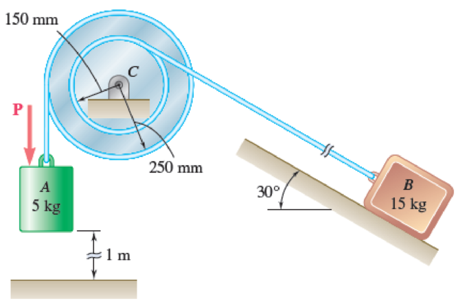
Fig. P17.14
(a)
Find the velocity of cylinder A as it strikes the ground.
Answer to Problem 17.14P
The velocity of the cylinder A when it strikes the ground is
Explanation of Solution
Given information:
The mass of the cylinder A is
The mass of the block B is
The radius of the outer pulley is
The radius of the inner pulley is
The centroidal radius of gyration is
The coefficient of friction between the surface and the block B is
The constant force applied at cylinder A is
Calculation:
Consider the acceleration due to gravity is
Consider the radius of the outer pulley as
Consider the radius of the inner pulley as
Find the velocity in the outer pulley
Here, the angular velocity of the pulley is
Find the velocity in the inner pulley
Substitute
Find the distance of the outer pulley
Here, the number of revolutions in the pulley C is
Find the distance of the inner pulley
Substitute
The initial total kinetic energy at rest is zero.
Find the mass moment of inertia in the pulley C
Here, the mass in the pulley C is
Substitute 15 kg for
Find the total kinetic energy
Substitute 5 kg for
Substitute 250 mm for
When
Substitute 150 mm for
Show free-body diagram the block B as in Figure 1.
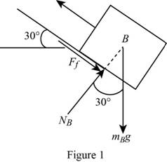
Resolve the vertical component of forces as follows;
Find the frictional force
Substitute 0.20 for
Apply the principle of work and energy for the cylinder A, the block B and the double pulley C as follows;
Substitute 200 N for P, 1 m for
Write the equation of work and energy for the system using the equation.
Substitute 0 for
Therefore, the velocity of the cylinder A when it strikes the ground is
(b)
Find the total distance the block B moves before coming to rest.
Answer to Problem 17.14P
The total distance travelled by the block B before coming to rest is
Explanation of Solution
Given information:
The mass of the cylinder A is
The mass of the block B is
The radius of the outer pulley is
The radius of the inner pulley is
The centroidal radius of gyration is
The coefficient of friction between the surface and the block B is
The constant force applied at cylinder A is
Calculation:
Refer part (a) for
Substitute
Substitute 150 mm for
Find the total kinetic energy
Substitute 5 kg for
At the final position, the system comes at rest.
The kinetic energy at rest is zero.
Apply the principle of work and energy for the block B as follows;
Here, the additional distance travelled by the block is
Substitute
Write the equation of work and energy for the system using the equation.
Substitute 132.3066 J for
Find the total distance
Substitute 0.6 m for
Therefore, the total distance travelled by the block B before coming to rest is
Want to see more full solutions like this?
Chapter 17 Solutions
VEC MECH 180-DAT EBOOK ACCESS(STAT+DYNA)
Additional Engineering Textbook Solutions
Vector Mechanics For Engineers
Concepts Of Programming Languages
Thermodynamics: An Engineering Approach
Modern Database Management
Electric Circuits. (11th Edition)
Starting Out with C++ from Control Structures to Objects (9th Edition)


- Procedure:1- Cartesian system, 2D3D,type of support2- Free body diagram3 - Find the support reactions4- If you find a negativenumber then flip the force5- Find the internal force3D∑Fx=0∑Fy=0∑Fz=0∑Mx=0∑My=0\Sigma Mz=02D\Sigma Fx=0\Sigma Fy=0\Sigma Mz=05- Use method of sectionand cut the elementwhere you want to findthe internal force andkeep either side of thearrow_forwardProcedure: 1- Cartesian system, 2(D)/(3)D, type of support 2- Free body diagram 3 - Find the support reactions 4- If you find a negative number then flip the force 5- Find the internal force 3D \sum Fx=0 \sum Fy=0 \sum Fz=0 \sum Mx=0 \sum My=0 \Sigma Mz=0 2D \Sigma Fx=0 \Sigma Fy=0 \Sigma Mz=0 5- Use method of section and cut the element where you want to find the internal force and keep either side of the sectionarrow_forwardProcedure: 1- Cartesian system, 2(D)/(3)D, type of support 2- Free body diagram 3 - Find the support reactions 4- If you find a negative number then flip the force 5- Find the internal force 3D \sum Fx=0 \sum Fy=0 \sum Fz=0 \sum Mx=0 \sum My=0 \Sigma Mz=0 2D \Sigma Fx=0 \Sigma Fy=0 \Sigma Mz=0 5- Use method of section and cut the element where you want to find the internal force and keep either side of the sectionarrow_forward
- For each system below with transfer function G(s), plot the pole(s) on the s-plane. and indicate whether the system is: (a) "stable" (i.e., a bounded input will always result in a bounded output), (b) "marginally stable," or (c) "unstable" Sketch a rough graph of the time response to a step input. 8 a) G(s) = 5-5 8 b) G(s) = c) G(s) = = s+5 3s + 8 s² - 2s +2 3s +8 d) G(s): = s²+2s+2 3s+8 e) G(s): = s² +9 f) G(s): 8 00 == Sarrow_forwardPlease answer the following question. Include all work and plase explain. Graphs are provided below. "Consider the Mg (Magnesium) - Ni (Nickel) phase diagram shown below. This phase diagram contains two eutectic reactions and two intermediate phases (Mg2Ni and MgNi2). At a temperature of 505oC, determine what the composition of an alloy would need to be to contain a mass fraction of 0.20 Mg and 0.80 Mg2Ni."arrow_forwardThe triangular plate, having a 90∘∘ angle at AA, supports the load PP = 370 lblb as shown in (Figure 1).arrow_forward
- Design a 4-bar linkage to carry the body in Figure 1 through the two positions P1 and P2 at the angles shown in the figure. Use analytical synthesis with the free choice values z = 1.075, q= 210°, ß2 = −27° for left side and s = 1.24, y= 74°, ½ = − 40° for right side. φ 1.236 P2 147.5° 210° 2.138 P1 Figure 1 Xarrow_forwardDesign a 4-bar linkage to carry the body in Figure 1 through the two positions P1 and P2 at the angles shown in the figure. Use analytical synthesis with the free choice values z = 1.075, q= 210°, B₂ = −27° for left side and s = 1.24, y= 74°, ½ = − 40° for right side. 1.236 P2 147.5° 210° P1 Figure 1 2.138 Xarrow_forwardcan you explain how in a coordinate frame transformation: v = {v_n}^T {n-hat} and then it was found that {n-hat} = [C]^T {b-hat} so v_n = {v_n}^T [C]^T {b-hat}, how does that equation go from that to this --> v_n = [C]^T v_barrow_forward
- 6) If (k = 0,7 cm) find Imax for figure below. 225mm 100mm ثلاثاء. 100mm 150mm 75mm Ans: Tmax=45:27 N/cm F-400 Narrow_forwardThe man has a weight W and stands halfway along the beam. The beam is not smooth, but the planes at A and B are smooth (and plane A is horizontal). Determine the magnitude of the tension in the cord in terms of W and θ.arrow_forwardDetermine the reactions at the two supports for this plate. Express the reactions in Cartesian vector form.arrow_forward
 Elements Of ElectromagneticsMechanical EngineeringISBN:9780190698614Author:Sadiku, Matthew N. O.Publisher:Oxford University Press
 Mechanics of Materials (10th Edition)Mechanical EngineeringISBN:9780134319650Author:Russell C. HibbelerPublisher:PEARSON
 Thermodynamics: An Engineering ApproachMechanical EngineeringISBN:9781259822674Author:Yunus A. Cengel Dr., Michael A. BolesPublisher:McGraw-Hill Education
 Control Systems EngineeringMechanical EngineeringISBN:9781118170519Author:Norman S. NisePublisher:WILEY
 Mechanics of Materials (MindTap Course List)Mechanical EngineeringISBN:9781337093347Author:Barry J. Goodno, James M. GerePublisher:Cengage Learning
 Engineering Mechanics: StaticsMechanical EngineeringISBN:9781118807330Author:James L. Meriam, L. G. Kraige, J. N. BoltonPublisher:WILEY