
Concept explainers
Videos
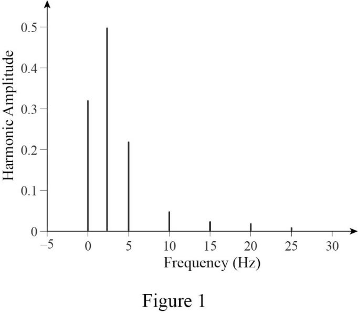
Sketch the line spectrum for the waveform shown in Figure 17.31.
Answer to Problem 15E
The line spectrum for the given waveform is sketched as shown in Figure 1.
Explanation of Solution
Given data:
Refer to Figure 17.31 in the textbook.
Formula used:
Write the general expression for Fourier series expansion.
Write the general expression for Fourier series coefficient
Write the general expression for Fourier series coefficient
Write the general expression for Fourier series coefficient
Write the expression to calculate the fundamental angular frequency.
Here,
Calculation:
In the given Figure 17.31, the time period is
The function
Substitute 0.4 for T in equation (5) to find
Applying equation (6) in equation (2) to find
Simplify the above equation as follows,
For half wave symmetry and even symmetry,
For all values of ‘n’,
Applying equation (6) in equation (3) to find the value of coefficient
Consider the function,
Consider,
On differentiating the above expression,
Equation (8) will be follows,
In the above equation, consider,
By applying linearity,
In equation (10),
consider,
Let,
Equation (11) will be as follows,
Similarly, in equation (10),
consider,
Let,
Equation (12) will be as follows,
Substitute the values of m and l in equation (10) as follows,
Substitute the value of y in equation (9) as follows,
Therefore,
On applying the limits,
Simplify the equation as follows,
Simplify the equation as follows,
Substitute the value of
Converting the equation (1) which is in angular frequency into frequency.
Substitute the value of
By considering
For
For
The sketch for the line spectrum is shown in Figure 1.
Conclusion:
Thus, the line spectrum for the given waveform is sketched as shown in Figure 1.
Want to see more full solutions like this?
Chapter 17 Solutions
ENGINEERING CIRCUIT...(LL)>CUSTOM PKG.<


- 11.32 A Y-D ideal three-phase transformer with a turns ratio of1 : 10 supplies a 32 kVA load at a line voltage of 208 V. Determinethe line voltage and line current at the primary sidearrow_forward11.33 A D-Y ideal three-phase transformer supplies a 32-kVAload at a line voltage of 240 V. If the line voltage at the primaryside is 51.96 V, what is the turns ratio?arrow_forwardI would like assistance with the electrical system of a streetcar/train, specifically in performing calculations related to speed, torque, and power for the motor and the train.Streetcar Gear SystemFrom my research, I have found that streetcars typically do not use traditional gear systems. Instead, the motor directly drives the truck (the assembly that holds the wheels and axles) to achieve the desired speed and torque required by the vehicle. The motor's speed and torque are controlled by a control box, which regulates the motor's performance according to the operational requirements. Truck LimitationsThe truck that will be used has certain limitations, such as: Maximun allowable speed: 50 mph Maximum motor output: 75 hp Motor specification: The specification of the motor is the following:Output power 200 HPSpeed 1150/2000 RPMArm’s voltage 600 VArm’s current 317 AFields volts 220 VField Amps 8/3Field Winding CompoundTorque calculation of the…arrow_forward
- 7. Find the currents I₁ and 12 in the following circuit, (16 points) - node V=IR 18ΚΩ 12ΚΩ RE 12 V + ww -Supernode 6ΚΩ 4k9k 12 RE22arrow_forward"Can you explain the method of choosing the direction?" Question- A plane wave in a non-magnetic medium = Нр 1 has an electric field- E = 50 sin(10®t +2)ây V m The standard equation of the electric field is- How can E = Eosin(t + Bây V m ✓ explan how (C. i)- The direction of the propagation is-âk = - âz the direction |arrow_forwardExpress this graph/signal as a sum of singularity functions. Please give a proper solution.arrow_forward
- 2) A 208 V, four-pole, 60 Hz, Y-connected, wound-rotor induction motor has a rated power of 30 HP. The components of its equivalent circuit are R1 = 0.100 R2 = 0.070 XM = 10.0 X1 = 0.210 X2 = 0.210 Pmec = 500 W Psup ~ 0 Pcore = 400 W For a slip of 0.05, find: a) The line current b) The stator copper losses PcE c) The air gap power PEF d) The power converted from mechanical to electrical form Pconv e) The induced torque _ind f) load torque _load g) The total efficiency of the machine h) The speed of the motor in revolutions per minute and in radians per secondarrow_forward5. There are three sources that would affect the current flow in this circuit. Find the current through the 4k2 resistor that is caused solely by the 24V source (i.e., remove the 2mA and 12V sources using the correct methods). (20 points) 24 V + 9k, ww www 4kS 2mA 24ΚΩ www ++ 12V www 6k 24ΚΩarrow_forward"Can you explain the method of finding the direction?" the electric field in free space is given by ety E: 50 Cos [2π 10 t - Bz ] a) find the direction of the wave propagation b) Calculate W, B, A, S V/marrow_forward
- Athle phase a.c. distributor AB has: The distance from A to B is 500 m. The distance from A to C is 800 m. The impedance of each section is (6+j 8) /km. A B C The voltage at the far end is maintained at 250 volt. Find: sending voltage, sending current, supply power factor and 80 A 60 A total voltage drop. 0.8 lag. P.f 0.6 lead. p.farrow_forwardThe transfer function H(s) = Y(s)/X(s) = Vo(s)/Vi(s) should be found from the circuit given that the initial conditions are equal to 0. Do not answer using AI Chatbots. PLEASEarrow_forwardA 10kW, 230V, long shunt compound DC generator has efficiency = 82%, armature resistance = 0.15 ohms, series field resistance = 0.1 ohm, shunt field resistance = 100 ohms. What are: armature current, armature voltage across the brushes, generated emf, total copper losses, and horsepower of prime mover?arrow_forward
 Introductory Circuit Analysis (13th Edition)Electrical EngineeringISBN:9780133923605Author:Robert L. BoylestadPublisher:PEARSON
 Delmar's Standard Textbook Of ElectricityElectrical EngineeringISBN:9781337900348Author:Stephen L. HermanPublisher:Cengage Learning
 Programmable Logic ControllersElectrical EngineeringISBN:9780073373843Author:Frank D. PetruzellaPublisher:McGraw-Hill Education
 Fundamentals of Electric CircuitsElectrical EngineeringISBN:9780078028229Author:Charles K Alexander, Matthew SadikuPublisher:McGraw-Hill Education
 Electric Circuits. (11th Edition)Electrical EngineeringISBN:9780134746968Author:James W. Nilsson, Susan RiedelPublisher:PEARSON
 Engineering ElectromagneticsElectrical EngineeringISBN:9780078028151Author:Hayt, William H. (william Hart), Jr, BUCK, John A.Publisher:Mcgraw-hill Education,