
Concept explainers
Videos
Obtain the exponential Fourier series for the signal in Fig. 17.54.
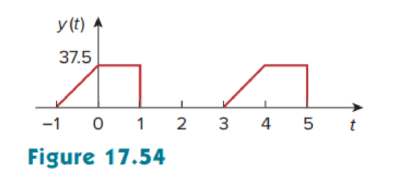
Find the exponential Fourier series for the signal in Figure 17.54.
Answer to Problem 11P
The exponential Fourier series
Explanation of Solution
Given data:
Refer to Figure 17.54 in the textbook.
Formula used:
Write the expression to calculate the fundamental angular frequency.
Here,
Write the general expression to calculate exponential Fourier series of
Here,
Write the expression to calculate exponential Fourier series coefficients.
Calculation:
The given waveform is drawn as Figure 1.
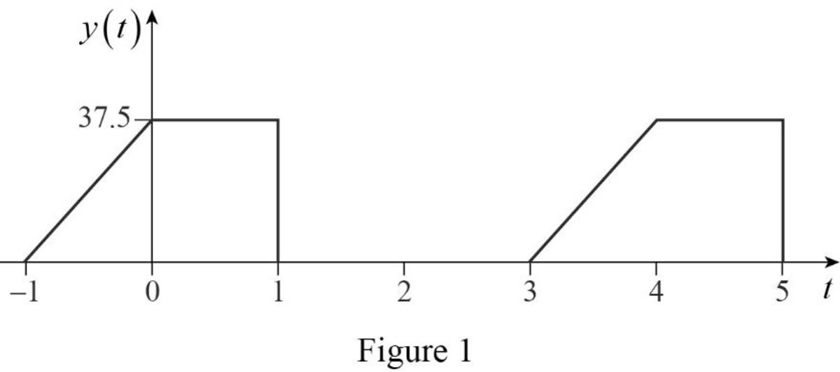
Refer to Figure 1. The Fourier series function is defined as,
The time period of the function in Figure 1 is,
Substitute
Substitute
Simplify the above equation to find
Simplify the above equation to find
Assume the following to reduce the equation (4).
Substitute the equations (5) in equation (4) to find
Consider the following integration formula.
Compare the equations (5) and (7) to simplify the equation (5).
Using the equation (7), the equation (5) can be reduced as,
Simplify the above equation to find
Simplify the above equation to find
Substitute
Substitute
Conclusion:
Thus, the exponential Fourier series
Want to see more full solutions like this?
Chapter 17 Solutions
Fundamentals of Electric Circuits


- theoretically and compare it with the test value. Report :- 1- Calculate the D.C. output Voltagearrow_forwardf 2- For resistive load, measured the output voltage by using oscilloscope, then sketch this wave.. 3- Measure the average values of Vɩ and Iɩ . 4- Repeat steps 2 & 3 but for R.L load.arrow_forwardA single-phase 10 kVA, 1000/100V transformer has the relative voltage parameters of: εrcc = 6%, εxcc = 8%, core losses Pfe = 200W and nominal copper losses of Pcu = 300W.A load of 2 < 30° Ω is connected to the secondary of the transformer. Determine using pu ́s calculations:to. The voltage in the primary, if the voltage of the secondary (at load) is 100 V.b. If the voltage in the primary remains constant at 1000 V, what would be the voltage at the load?c. The voltage regulation of the transformer under the conditions b.d. The efficiency of the transformer under the conditions b.arrow_forward
- 9.38 For the op-amp circuit of Fig. P9.38:(a) Obtain an expression for H(w) = Vo/Vs in standard form.(b) Generate spectral plots for the magnitude and phase ofH(w), given that R1 = 99 kW, R2 = 1 kW, and C = 0.1 μF.(c) What type of filter is it? What is its maximum gain?arrow_forwardA short 3-o transmission line with an impedance of (6+j 8)2 per phase has receiving end of 22000 kw, 120 KV, 0.8 lagging p.f. Determine (i) Sending voltage (ii) Sending current (iii) Sending power factor (iv) voltage regulation.arrow_forward9.37 For the op-amp circuit of Fig. P9.37:*(a) Obtain an expression for H(w) = Vo/Vs in standard form.(b) Generate spectral plots for the magnitude and phase ofH(w), given that R1 = 1 kW, R2 = 4 kW, and C = 1 μF.(c) What type of filter is it? What is its maximum gainarrow_forward
- I need a detailed drawing with explanation Solve es 4 = -20125 شكا +981X914 pv + 96852 الإنجليزية (second order differential I need an example on the subject the partition method and the Laplace method. Suggest an easy equations) and you solve it using and simple example for me and solve it using two methods, only one example. 750 01 95Parrow_forwardNot use ai pleasearrow_forwardし الإنجليزية (second order differential I need an example on the subject the partition method and the equations) and you solve it using Laplace method. Suggest an easy and simple example for me and solve it using two methods, only one example. الله X 9.01 P+96erarrow_forward
- I need an example on the subject (second order differential equations) and you solve it using the partition method and the Laplace method. Suggest an easy and simple example for me and solve it using two methods, only one example.arrow_forward5- Discuss your resultsarrow_forwardWrite a program to flash three LED's connected to ports (8, 9 & 10) respectively as shown below: (Note: T₁-T3-5s & T₂=3s) LED, (pin 10) 2. Suen LED₂ (pin 9) LED, (pin 8) T₁'T' T'arrow_forward
 Introductory Circuit Analysis (13th Edition)Electrical EngineeringISBN:9780133923605Author:Robert L. BoylestadPublisher:PEARSON
 Delmar's Standard Textbook Of ElectricityElectrical EngineeringISBN:9781337900348Author:Stephen L. HermanPublisher:Cengage Learning
 Programmable Logic ControllersElectrical EngineeringISBN:9780073373843Author:Frank D. PetruzellaPublisher:McGraw-Hill Education
 Fundamentals of Electric CircuitsElectrical EngineeringISBN:9780078028229Author:Charles K Alexander, Matthew SadikuPublisher:McGraw-Hill Education
 Electric Circuits. (11th Edition)Electrical EngineeringISBN:9780134746968Author:James W. Nilsson, Susan RiedelPublisher:PEARSON
 Engineering ElectromagneticsElectrical EngineeringISBN:9780078028151Author:Hayt, William H. (william Hart), Jr, BUCK, John A.Publisher:Mcgraw-hill Education,