
Concept explainers
The 6-kg rod BC connects a 10-kg disk centered at A to a 5-kg rod CD. The motion of the system is controlled by the couple M applied to disk A. Knowing that at the instant shown disk A has an angular velocity of 36 rad/s clockwise and no angular acceleration, determine (a) the couple M, (b) the components of the force exerted at C on rod BC.
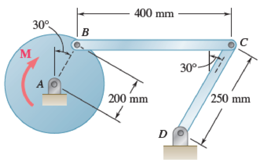
Fig. P16.135 and P16.136
(a)
Find the couple M.
Answer to Problem 16.135P
The couple M is
Explanation of Solution
Given information:
The mass of the rod BC is
The mass of the disk is
The mass of the rod CD is
The angular velocity is
The angular acceleration is
Calculation:
Consider the acceleration due to gravity as
Calculate the velocity of disk AB
Substitute
Calculate the velocity of rod BC
The velocity of disk AB is equal to the velocity of rod BC.
Substitute
Calculate the angular velocity of rod CD
Substitute
Apply the acceleration analysis as shown below.
Calculate the acceleration for disk AB
Substitute
Calculate the acceleration for rod BC
Substitute
Calculate the acceleration for rod CD
Substitute
Equating the components of Equations (1) and (2) as shown below.
Along x component.
Along y component.
Substitute
Calculate the acceleration of the mass centers as shown below.
Calculate the acceleration of mass center for disk AB
Calculate the acceleration of the mass center at P for rod BC
Substitute
Substitute
Calculate the acceleration of the mass center at Q for rod CD
Substitute
Calculate the inertial terms at mass centers as shown below.
The inertia terms at centers are
For disk AB.
For rod BC.
Substitute
For rod CD.
Substitute
Calculate the mass moment of inertia
For disk AB.
Substitute
For rod BC.
Substitute
For rod CD.
Substitute
Calculate the effective couples at mass centers as shown below.
The inertia terms at centers are
For disk AB.
For rod BC.
Substitute
For rod CD.
Substitute
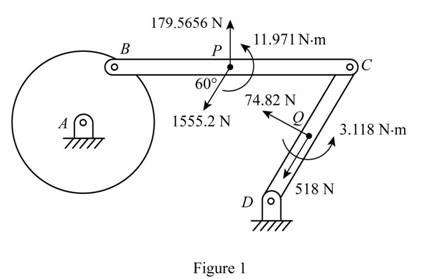
Sketch the effective force and couples on the system as shown in Figure 1.
Sketch the Free Body Diagram of the rod BC as shown in Figure 2.
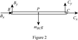
Refer to Figure 2.
Apply the Equilibrium of moment about B as shown below.
Substitute
Sketch the Free Body Diagram of the rod CD as shown in Figure 3.
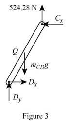
Refer to Figure 3.
Apply the Equilibrium of moment about D as shown below.
Substitute
Sketch the Free Body Diagram of the rod AB and BC as shown in Figure 4.
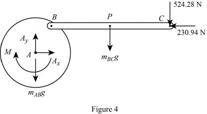
Refer to Figure 4.
Apply the Equilibrium of moment about A as shown below.
Substitute
Therefore, the couple M is
(b)
The components of force exerted at C on rod BC.
Answer to Problem 16.135P
The components of force exerted at C on rod BC is
Explanation of Solution
Given information:
The mass of the rod BC is
The mass of the disk is
The mass of the rod CD is
The angular velocity is
The angular acceleration is
Calculation:
Refer to part (a).
The components of force exerted at C on rod BC along x direction is
The components of force exerted at C on rod BC along y direction is
Therefore, the components of force exerted at C on rod BC is
Want to see more full solutions like this?
Chapter 16 Solutions
VEC MECH 180-DAT EBOOK ACCESS(STAT+DYNA)
Additional Engineering Textbook Solutions
Fluid Mechanics: Fundamentals and Applications
Electric Circuits. (11th Edition)
Experiencing MIS
Starting Out With Visual Basic (8th Edition)
Elementary Surveying: An Introduction To Geomatics (15th Edition)
Thermodynamics: An Engineering Approach
- (b) A steel 'hot rolled structural hollow section' column of length 5.75 m, has the cross-section shown in Figure Q.5(b) and supports a load of 750 kN. During service, it is subjected to axial compression loading where one end of the column is effectively restrained in position and direction (fixed) and the other is effectively held in position but not in direction (pinned). i) Given that the steel has a design strength of 275 MN/m², determine the load factor for the structural member based upon the BS5950 design approach using Datasheet Q.5(b). [11] ii) Determine the axial load that can be supported by the column using the Rankine-Gordon formula, given that the yield strength of the material is 280 MN/m² and the constant *a* is 1/30000. [6] 300 600 2-300 mm wide x 5 mm thick plates. Figure Q.5(b) L=5.75m Pinned Fixedarrow_forwardHelp ارجو مساعدتي في حل هذا السؤالarrow_forwardHelp ارجو مساعدتي في حل هذا السؤالarrow_forward
- Q2: For the following figure, find the reactions of the system. The specific weight of the plate is 500 lb/ft³arrow_forwardQ1: For the following force system, find the moments with respect to axes x, y, and zarrow_forwardQ10) Body A weighs 600 lb contact with smooth surfaces at D and E. Determine the tension in the cord and the forces acting on C on member BD, also calculate the reaction at B and F. Cable 6' 3' wwwarrow_forward
- Help ارجو مساعدتي في حل هذا السؤالarrow_forwardQ3: Find the resultant of the force system.arrow_forwardQuestion 1 A three-blade propeller of a diameter of 2 m has an activity factor AF of 200 and its ratio of static thrust coefficient to static torque coefficient is 10. The propeller's integrated lift coefficient is 0.3.arrow_forward
- (L=6847 mm, q = 5331 N/mm, M = 1408549 N.mm, and El = 8.6 x 10¹⁴ N. mm²) X A ΕΙ B L Y Marrow_forwardCalculate the maximum shear stress Tmax at the selected element within the wall (Fig. Q3) if T = 26.7 KN.m, P = 23.6 MPa, t = 2.2 mm, R = 2 m. The following choices are provided in units of MPa and rounded to three decimal places. Select one: ○ 1.2681.818 O 2. 25745.455 O 3. 17163.636 O 4. 10727.273 ○ 5.5363.636arrow_forwardIf L-719.01 mm, = 7839.63 N/m³, the normal stress σ caused by self-weight at the location of the maximum normal stress in the bar can be calculated as (Please select the correct value of σ given in Pa and rounded to three decimal places.) Select one: ○ 1. 1409.193 2. 845.516 O 3. 11273.545 ○ 4.8455.159 ○ 5.4509.418 6. 2818.386 7.5636.772arrow_forward
 Elements Of ElectromagneticsMechanical EngineeringISBN:9780190698614Author:Sadiku, Matthew N. O.Publisher:Oxford University Press
 Mechanics of Materials (10th Edition)Mechanical EngineeringISBN:9780134319650Author:Russell C. HibbelerPublisher:PEARSON
 Thermodynamics: An Engineering ApproachMechanical EngineeringISBN:9781259822674Author:Yunus A. Cengel Dr., Michael A. BolesPublisher:McGraw-Hill Education
 Control Systems EngineeringMechanical EngineeringISBN:9781118170519Author:Norman S. NisePublisher:WILEY
 Mechanics of Materials (MindTap Course List)Mechanical EngineeringISBN:9781337093347Author:Barry J. Goodno, James M. GerePublisher:Cengage Learning
 Engineering Mechanics: StaticsMechanical EngineeringISBN:9781118807330Author:James L. Meriam, L. G. Kraige, J. N. BoltonPublisher:WILEY


