
Videos
Disk B is at rest when it is brought into contact with disk A, which has an initial angular velocity ω0. (a) Show that the final angular velocities of the disks are independent of the coefficient of friction μk between the disks as long as μk ≠ 0. (b) Express the final angular velocity of disk A in terms of ω0 and the ratio of the masses of the two disks, mA/mB.
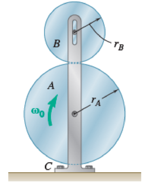
Fig. P16.43 and P16.44
(a)
Show that the final velocities of disk A and B are independent of coefficient of kinetic friction
Explanation of Solution
The mass of the disk A is
The mass of the disk B is
The initial angular velocity of the disk A is
The coefficient of the kinetic friction is
The radius of the disk A is
The radius of the disk B is
The acceleration due to gravity is g.
The time required for the disk to come to rest is t.
Calculation:
Calculate the mass moment of inertia of the disk A
Calculate the mass moment of inertia of the disk B
Calculate the load of the disk A
Calculate the load of the disk B
Show the free body diagram of the disk B as in Figure 1.
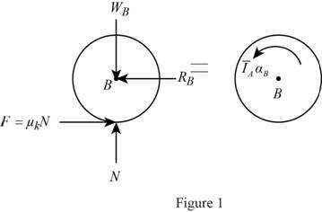
Here,
Refer to Figure 1.
Calculate the vertical forces by applying the equation of equilibrium:
Sum of vertical forces is equal to 0.
Substitute
Calculate the magnitude of the friction force
Substitute
Calculate the horizontal forces by applying the equation of equilibrium:
Sum of horizontal forces is equal to 0.
Substitute
Calculate the angular acceleration of the disk B
Calculate the moment about point B by applying the equation of equilibrium:
Substitute
Show the free body diagram of the disk A as in Figure 2.
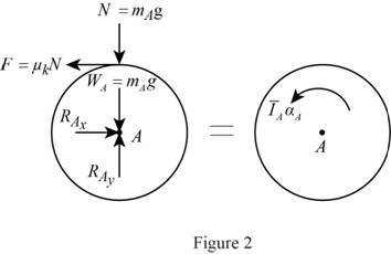
Here,
Refer to Figure 2.
Calculate the horizontal forces by applying the equation of equilibrium:
Sum of horizontal forces is equal to 0.
Substitute
Calculate the vertical forces by applying the equation of equilibrium:
Sum of vertical forces is equal to 0.
Substitute
Calculate the angular acceleration of the disk A
Calculate the moment about point A by applying the equation of equilibrium:
Substitute
The angular velocity of the disk A
Substitute
The angular velocity of the disk B
Substitute
While there is no slipping between disk A and B, their velocity ratio is same.
Show the free body diagram of the system as in Figure 3.
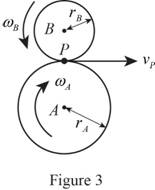
Refer to Figure 3.
The velocity of pinion
Substitute
Calculate the angular velocity of the disk A
Substitute
Calculate the angular velocity of the disk B
Substitute
From Equation (5) and (6), it is clear that the final velocities of disk A and B are independent of coefficient of kinetic friction
(b)
Express the final angular velocity of disk A in terms of
Answer to Problem 16.44P
The final angular velocity of disk A in terms of
Explanation of Solution
The mass of the disk A is
The mass of the disk B is
The initial angular velocity of the disk A is
The coefficient of the kinetic friction is
The radius of the disk A is
The radius of the disk B is
The acceleration due to gravity is g.
The time required for the disk to come to rest is t.
Calculation:
Refer to part (a).
Calculate the final angular velocity of disk A in terms of
Refer Equation (5).
Hence, the final angular velocity of disk A in terms of
Want to see more full solutions like this?
Chapter 16 Solutions
Connect 1 Semester Access Card for Vector Mechanics for Engineers: Statics and Dynamics
Additional Engineering Textbook Solutions
Elementary Surveying: An Introduction To Geomatics (15th Edition)
Thermodynamics: An Engineering Approach
Electric Circuits. (11th Edition)
Database Concepts (8th Edition)
Modern Database Management
Automotive Technology: Principles, Diagnosis, And Service (6th Edition) (halderman Automotive Series)


- 2. Figure below shows a U-tube manometer open at both ends and containing a column of liquid mercury of length l and specific weight y. Considering a small displacement x of the manometer meniscus from its equilibrium position (or datum), determine the equivalent spring constant associated with the restoring force. Datum Area, Aarrow_forward1. The consequences of a head-on collision of two automobiles can be studied by considering the impact of the automobile on a barrier, as shown in figure below. Construct a mathematical model (i.e., draw the diagram) by considering the masses of the automobile body, engine, transmission, and suspension and the elasticity of the bumpers, radiator, sheet metal body, driveline, and engine mounts.arrow_forward3.) 15.40 – Collar B moves up at constant velocity vB = 1.5 m/s. Rod AB has length = 1.2 m. The incline is at angle = 25°. Compute an expression for the angular velocity of rod AB, ė and the velocity of end A of the rod (✓✓) as a function of v₂,1,0,0. Then compute numerical answers for ȧ & y_ with 0 = 50°.arrow_forward
- 2.) 15.12 The assembly shown consists of the straight rod ABC which passes through and is welded to the grectangular plate DEFH. The assembly rotates about the axis AC with a constant angular velocity of 9 rad/s. Knowing that the motion when viewed from C is counterclockwise, determine the velocity and acceleration of corner F.arrow_forward500 Q3: The attachment shown in Fig.3 is made of 1040 HR. The static force is 30 kN. Specify the weldment (give the pattern, electrode number, type of weld, length of weld, and leg size). Fig. 3 All dimension in mm 30 kN 100 (10 Marks)arrow_forward(read image) (answer given)arrow_forward
- A cylinder and a disk are used as pulleys, as shown in the figure. Using the data given in the figure, if a body of mass m = 3 kg is released from rest after falling a height h 1.5 m, find: a) The velocity of the body. b) The angular velocity of the disk. c) The number of revolutions the cylinder has made. T₁ F Rd = 0.2 m md = 2 kg T T₂1 Rc = 0.4 m mc = 5 kg ☐ m = 3 kgarrow_forward(read image) (answer given)arrow_forward11-5. Compute all the dimensional changes for the steel bar when subjected to the loads shown. The proportional limit of the steel is 230 MPa. 265 kN 100 mm 600 kN 25 mm thickness X Z 600 kN 450 mm E=207×103 MPa; μ= 0.25 265 kNarrow_forward
- T₁ F Rd = 0.2 m md = 2 kg T₂ Tz1 Rc = 0.4 m mc = 5 kg m = 3 kgarrow_forward2. Find a basis of solutions by the Frobenius method. Try to identify the series as expansions of known functions. (x + 2)²y" + (x + 2)y' - y = 0 ; Hint: Let: z = x+2arrow_forward1. Find a power series solution in powers of x. y" - y' + x²y = 0arrow_forward
 Elements Of ElectromagneticsMechanical EngineeringISBN:9780190698614Author:Sadiku, Matthew N. O.Publisher:Oxford University Press
 Mechanics of Materials (10th Edition)Mechanical EngineeringISBN:9780134319650Author:Russell C. HibbelerPublisher:PEARSON
 Thermodynamics: An Engineering ApproachMechanical EngineeringISBN:9781259822674Author:Yunus A. Cengel Dr., Michael A. BolesPublisher:McGraw-Hill Education
 Control Systems EngineeringMechanical EngineeringISBN:9781118170519Author:Norman S. NisePublisher:WILEY
 Mechanics of Materials (MindTap Course List)Mechanical EngineeringISBN:9781337093347Author:Barry J. Goodno, James M. GerePublisher:Cengage Learning
 Engineering Mechanics: StaticsMechanical EngineeringISBN:9781118807330Author:James L. Meriam, L. G. Kraige, J. N. BoltonPublisher:WILEY