
Fundamentals of Electric Circuits
6th Edition
ISBN: 9780078028229
Author: Charles K Alexander, Matthew Sadiku
Publisher: McGraw-Hill Education
expand_more
expand_more
format_list_bulleted
Videos
Textbook Question
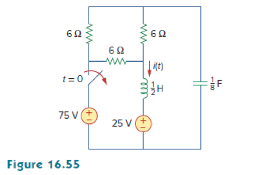
Chapter 16, Problem 32P
For the network in Fig. 16.55, solve for i(t) for t > 0.
Expert Solution & Answer
Want to see the full answer?
Check out a sample textbook solution
Students have asked these similar questions
3. Consider the following closed-loop system as shown in the figure.
16
Ge(s)
s(s + 4)
Suppose Ge(s) is a PID controller with Kp = 1, KD = 2 and K₁ = 3.
a) Find the controller transfer function G₁(s).
b) Find the open-loop transfer function.
c) Find the closed-loop transfer function.
Exercise 3-12: Find the Thévenin equivalent of the circuit
to the left of terminals (a, b) in Fig. E3.12, and then
determine the current I.
502
5 Ω
0.6 Ω
a
3Ω
ΣΙΩ
b
20 V
1 +
2027
15A
Figure E3.12
solve and show work
Chapter 16 Solutions
Fundamentals of Electric Circuits
Ch. 16.2 - Determine vo(t) in the circuit of Fig. 16.6,...Ch. 16.2 - Prob. 2PPCh. 16.2 - Prob. 3PPCh. 16.3 - For the circuit shown in Fig. 16.12 with the same...Ch. 16.3 - Prob. 5PPCh. 16.3 - The initial energy in the circuit of Fig. 16.17 is...Ch. 16.4 - Prob. 7PPCh. 16.4 - Prob. 8PPCh. 16.4 - Prob. 9PPCh. 16.5 - Obtain the state variable model for the circuit...
Ch. 16.5 - Prob. 11PPCh. 16.5 - Prob. 12PPCh. 16.6 - For what value of is the circuit in Fig. 16.29...Ch. 16.6 - Prob. 14PPCh. 16.6 - Prob. 15PPCh. 16.6 - Synthesize the function Vo(s)Vin=2ss2+6s+10 using...Ch. 16 - Prob. 1RQCh. 16 - The current through an RL series circuit with...Ch. 16 - Prob. 3RQCh. 16 - Prob. 4RQCh. 16 - Prob. 5RQCh. 16 - Prob. 6RQCh. 16 - Prob. 7RQCh. 16 - Prob. 8RQCh. 16 - Prob. 9RQCh. 16 - Prob. 10RQCh. 16 - The current in an RLC circuit is described by...Ch. 16 - The differential equation that describes the...Ch. 16 - Prob. 3PCh. 16 - If R = 20 , L = 0.6 H, what value of C will make...Ch. 16 - The responses of a series RLC circuit are vc(t) =...Ch. 16 - Prob. 6PCh. 16 - Prob. 7PCh. 16 - Prob. 8PCh. 16 - Prob. 9PCh. 16 - The step responses of a series RLC circuit are Vc...Ch. 16 - The step response of a parallel RLC circuit is v =...Ch. 16 - Prob. 12PCh. 16 - Prob. 13PCh. 16 - Prob. 14PCh. 16 - For the circuit in Fig. 16.38. calculate the value...Ch. 16 - The capacitor in the circuit of Fig. 16.39 is...Ch. 16 - If is(t) = 7.5e2t u(t) A in the circuit shown in...Ch. 16 - Find v(t), t 0 in the circuit of Fig. 16.41. Let...Ch. 16 - The switch in Fig. 16.42 moves from position A to...Ch. 16 - Find i(t) for t 0 in the circuit of Fig. 16.43.Ch. 16 - In the circuit of Fig. 16.44, the switch moves...Ch. 16 - Find the voltage across the capacitor as a...Ch. 16 - Obtain v (t) for t 0 in the circuit of Fig....Ch. 16 - The switch in the circuit of Fig. 16.47 has been...Ch. 16 - Calculate v(t) for t 0 in the circuit of Fig....Ch. 16 - Prob. 26PCh. 16 - Find v (t) for t 0 in the circuit in Fig. 16.50.Ch. 16 - For the circuit in Fig. 16.51, find v(t) for t 0.Ch. 16 - Prob. 29PCh. 16 - Find vo(t), for all t 0, in the circuit of Fig....Ch. 16 - Prob. 31PCh. 16 - For the network in Fig. 16.55, solve for i(t) for...Ch. 16 - Using Fig. 16.56, design a problem to help other...Ch. 16 - Prob. 34PCh. 16 - Prob. 35PCh. 16 - Prob. 36PCh. 16 - Prob. 37PCh. 16 - The switch in the circuit of Fig. 16.61 is moved...Ch. 16 - Prob. 39PCh. 16 - Prob. 40PCh. 16 - Prob. 41PCh. 16 - Prob. 42PCh. 16 - Prob. 43PCh. 16 - Prob. 44PCh. 16 - Find v(t) for t 0 in the circuit in Fig. 16.68.Ch. 16 - Prob. 46PCh. 16 - Determine io(t) in the network shown in Fig....Ch. 16 - Prob. 48PCh. 16 - Find i0(t) for t 0 in the circuit in Fig. 16.72....Ch. 16 - Prob. 50PCh. 16 - In the circuit of Fig. 16.74, find i(t) for t 0.Ch. 16 - Prob. 52PCh. 16 - In the circuit of Fig. 16.76, the switch has been...Ch. 16 - Prob. 54PCh. 16 - Prob. 55PCh. 16 - Calculate io(t) for t 0 in the network of Fig....Ch. 16 - Prob. 57PCh. 16 - Prob. 58PCh. 16 - Find vo(t) in the circuit of Fig. 16.82 if vx(0) =...Ch. 16 - Prob. 60PCh. 16 - Prob. 61PCh. 16 - Using Fig. 16.85, design a problem to help other...Ch. 16 - Consider the parallel RLC circuit of Fig. 16.86....Ch. 16 - The switch in Fig. 16.87 moves from position 1 to...Ch. 16 - For the RLC circuit shown in Fig. 16.88, find the...Ch. 16 - For the op amp circuit in Fig. 16.89, find v0(t)...Ch. 16 - Given the op amp circuit in Fig. 16.90, if v1(0+)...Ch. 16 - Prob. 68PCh. 16 - Prob. 69PCh. 16 - Using Fig. 16.93, design a problem to help other...Ch. 16 - Prob. 71PCh. 16 - The transfer function of a system is H(s)=s23s+1...Ch. 16 - Prob. 73PCh. 16 - Design a problem to help other students better...Ch. 16 - Prob. 75PCh. 16 - For the circuit in Fig. 16.95, find H(s) =...Ch. 16 - Obtain the transfer function H(s) = VoVs for the...Ch. 16 - Prob. 78PCh. 16 - For the circuit in Fig. 16.97, find: (a) I1/Vs (b)...Ch. 16 - Refer to the network in Fig. 16.98. Find the...Ch. 16 - Prob. 81PCh. 16 - Prob. 82PCh. 16 - Refer to the RL circuit in Fig. 16.101. Find: (a)...Ch. 16 - A parallel RL circuit has R = 4 and L = 1 H. The...Ch. 16 - Prob. 85PCh. 16 - Prob. 86PCh. 16 - Prob. 87PCh. 16 - Prob. 88PCh. 16 - Develop the state equations for the circuit shown...Ch. 16 - Prob. 90PCh. 16 - Prob. 91PCh. 16 - Prob. 92PCh. 16 - Prob. 93PCh. 16 - Prob. 94PCh. 16 - Prob. 95PCh. 16 - Prob. 96PCh. 16 - A system is formed by cascading two systems as...Ch. 16 - Determine whether the op amp circuit in Fig....Ch. 16 - It is desired realize the transfer function...Ch. 16 - Prob. 100PCh. 16 - Prob. 101PCh. 16 - Synthesize the transfer function...Ch. 16 - Prob. 103CPCh. 16 - Prob. 104CPCh. 16 - Prob. 105CP
Knowledge Booster


Learn more about
Need a deep-dive on the concept behind this application? Look no further. Learn more about this topic, electrical-engineering and related others by exploring similar questions and additional content below.Similar questions
- Don't use ai to answer I will report you answerarrow_forwardvalues. 4. Discussion: DEPA الأمهريائية RING Compare between theoretic bination effect of Kp and KI at first order and second order systems regarding steady-state errors and transient responses with the practical. In Experiment PI Controllerarrow_forwardⓇ 1. Discuss the relationship between DMA-out and A-out signals. 2. Explain the results of steps 3 and 4 in Experiment 16-2. Unit 16 CVSD System Table 16-2 CVSD demodulator (CLK out - 90KHz) A-in Input Signal DMD-out Waveform & Frequency DMA-out Waveform & Frequency TKHz 1Vpp Sinewave 3KHz 1Vpp Sinewave 200Hz 1Vpp Sinewavearrow_forward
- 3. Describe the function of the lowpass filter (LPF) used in CVSD system.arrow_forwardDon't use ai to answer I will report you answerarrow_forwardRL +Vcc a VCE 2. a) For the direct coupled class A amplifier shown, derive the expression for efficiency in terms of maximum and minimum values of currents and voltages. b) Determine the maximum efficiency of this circuit. c) Derive the expression for maximum power dissipation. www 9 www RB in VBEarrow_forward
- The joint probability density function of two discrete random variables X and Y is given by p(x, y)=c(2x+y), where x and y can assume all integers such that 0≤ x≤2, 0≤ y ≤ 3, and p (x, y)= 0 otherwise. a) Find the value of the constant c. (c) Find P(X≥1, Y≤2). (b) Find P(X=2, Y= 1).arrow_forwardA wattmeter is connected with the positive lead on phase "a" of a three-phase system. The negative lead is connected to phase "b". A separate wattmeter has the positive lead connected to phase "c". The negative lead of this wattmeter is connected also to phase "b". If the input voltage is 208 volts line-to- line, the phase sequence is "abc" and the load is 1200 ohm resistors connected in "Y", what is the expected reading of each of the wattmeters? (Hint: draw a phasor diagram)arrow_forward1- Write the mesh equation for the circuit below. Solve the equations using Crame method (matrix and determinant), and find the current of resistor 4 ohm. 6 A www 10 Ω w 6Ω www 12 V + 402 www 12 Ω 2- Write the nodal equations for the circuit below. You do not need to solve the equation just write the matrix equation. R3 ww 8Ω R₁ 201 5 A 12 3A R₂40arrow_forward
arrow_back_ios
SEE MORE QUESTIONS
arrow_forward_ios
Recommended textbooks for you
 Introductory Circuit Analysis (13th Edition)Electrical EngineeringISBN:9780133923605Author:Robert L. BoylestadPublisher:PEARSON
 Delmar's Standard Textbook Of ElectricityElectrical EngineeringISBN:9781337900348Author:Stephen L. HermanPublisher:Cengage Learning
 Programmable Logic ControllersElectrical EngineeringISBN:9780073373843Author:Frank D. PetruzellaPublisher:McGraw-Hill Education
 Fundamentals of Electric CircuitsElectrical EngineeringISBN:9780078028229Author:Charles K Alexander, Matthew SadikuPublisher:McGraw-Hill Education
 Electric Circuits. (11th Edition)Electrical EngineeringISBN:9780134746968Author:James W. Nilsson, Susan RiedelPublisher:PEARSON
 Engineering ElectromagneticsElectrical EngineeringISBN:9780078028151Author:Hayt, William H. (william Hart), Jr, BUCK, John A.Publisher:Mcgraw-hill Education,
Introductory Circuit Analysis (13th Edition)
Electrical Engineering
ISBN:9780133923605
Author:Robert L. Boylestad
Publisher:PEARSON
Delmar's Standard Textbook Of Electricity
Electrical Engineering
ISBN:9781337900348
Author:Stephen L. Herman
Publisher:Cengage Learning
Programmable Logic Controllers
Electrical Engineering
ISBN:9780073373843
Author:Frank D. Petruzella
Publisher:McGraw-Hill Education
Fundamentals of Electric Circuits
Electrical Engineering
ISBN:9780078028229
Author:Charles K Alexander, Matthew Sadiku
Publisher:McGraw-Hill Education
Electric Circuits. (11th Edition)
Electrical Engineering
ISBN:9780134746968
Author:James W. Nilsson, Susan Riedel
Publisher:PEARSON
Engineering Electromagnetics
Electrical Engineering
ISBN:9780078028151
Author:Hayt, William H. (william Hart), Jr, BUCK, John A.
Publisher:Mcgraw-hill Education,
Systems and Simulation - Lecture 3: Modelling of Mechanical systems; Author: bioMechatronics Lab;https://www.youtube.com/watch?v=fMcDdyoC9mA;License: Standard Youtube License