
Concept explainers
Design a problem to better understand the circuit analysis using Laplace transform using Figure 16.36.
Explanation of Solution
Problem design:
Find the value of voltage across resistor
Formula used:
Write a general expression to calculate the impedance of a resistor in s-domain.
Here,
Write a general expression to calculate the impedance of an inductor in s-domain.
Here,
Write a general expression to calculate the impedance of a capacitor in s-domain.
Here,
Calculation:
The given circuit is redrawn as shown in Figure 1.
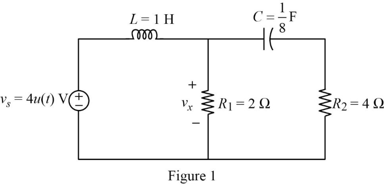
Apply Laplace transform to the voltage source
Substitute
Substitute
Substitute
Substitute
Convert the Figure 1 into s-domain.
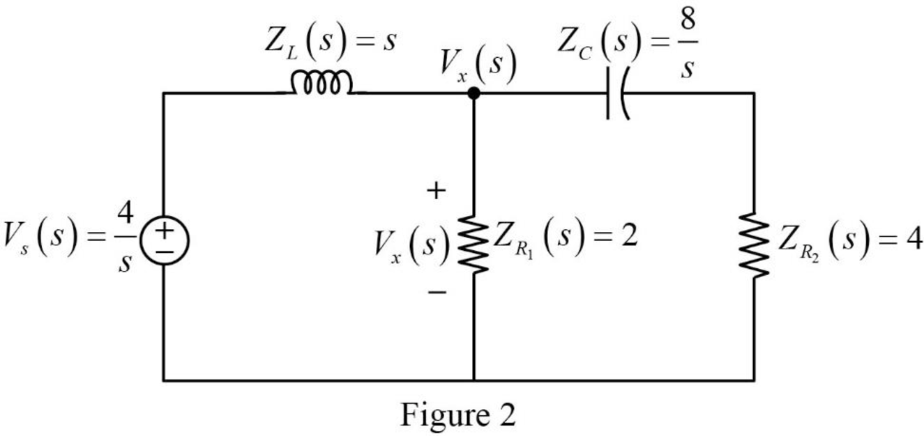
Apply Kirchhoff’s current law at node
Simplify the above equation as follows,
Simplify the above equation to find
From equation (4), the characteristic equation is written as follows,
Write an expression to calculate the roots of characteristic equation
Here,
Compare equation (5) with quadratic equation
Substitute
Now, the equation (4) is written as follows,
Take partial fraction for equation (7).
The equation (8) can also be written as follows,
Simplify the above equation as follows,
Substitute
Simplify the above equation as follows,
Simplify the above equation to find
Substitute
Simplify the above equation as follows,
Simplify the above equation to find
Substitute
Simplify the above equation as follows,
Simplify the above equation to find
Substitute
Take inverse Laplace transform for equation (10) to find
Simplify the above equation to find
Conclusion:
Thus, the problem to better understand the circuit analysis using Laplace transform is designed.
Want to see more full solutions like this?
Chapter 16 Solutions
Fundamentals of Electric Circuits


- What are the four conditions that must be met before a generator is connected to a 3 phase system?arrow_forwardPlease solve this question step by step and handwritten and do not use chat gpt or ai tools thank you very much!arrow_forwardPlease solve question c and d step by step and handwritten and do not use chat gpt or ai tools thank you very much!arrow_forward
- Please solve questions d,e,f step by step and handwritten and do not use chat gpt or ai tools thank you very much!arrow_forwardPlease solve this question step by step and handwritten and do not use chat gpt or ai tools thank you very much!arrow_forwardPlease solve question c,d,e step by step and handwritten and do not use chat gpt or ai tools thank you very much!arrow_forward
- Q1: Design a logic circuit for the finite-state machine described by the assigned table in Fig. 1: Using D flip-flops. a. b. Using T flip-flops. Present Next State Output State x=0 x=0 YE Y₁Y Y₁Y Z 00 00 01 0 0 от 00 0 0 10 00 10 11 00 10 0arrow_forwardFind Va and Vb using mesh analysisarrow_forwardFind Va and Vb using Mesh analysisarrow_forward
- Find Va and Vb using nodal analysisarrow_forward2. Using the approximate method, hand sketch the Bode plot for the following transfer functions. a) H(s) = 10 b) H(s) (s+1) c) H(s): = 1 = +1 100 1000 (s+1) 10(s+1) d) H(s) = (s+100) (180+1)arrow_forwardQ4: Write VHDL code to implement the finite-state machine described by the state Diagram in Fig. 1. Fig. 1arrow_forward
 Introductory Circuit Analysis (13th Edition)Electrical EngineeringISBN:9780133923605Author:Robert L. BoylestadPublisher:PEARSON
 Delmar's Standard Textbook Of ElectricityElectrical EngineeringISBN:9781337900348Author:Stephen L. HermanPublisher:Cengage Learning
 Programmable Logic ControllersElectrical EngineeringISBN:9780073373843Author:Frank D. PetruzellaPublisher:McGraw-Hill Education
 Fundamentals of Electric CircuitsElectrical EngineeringISBN:9780078028229Author:Charles K Alexander, Matthew SadikuPublisher:McGraw-Hill Education
 Electric Circuits. (11th Edition)Electrical EngineeringISBN:9780134746968Author:James W. Nilsson, Susan RiedelPublisher:PEARSON
 Engineering ElectromagneticsElectrical EngineeringISBN:9780078028151Author:Hayt, William H. (william Hart), Jr, BUCK, John A.Publisher:Mcgraw-hill Education,