
Videos
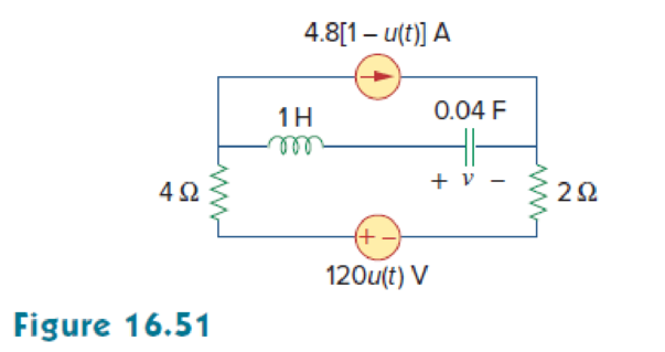
For the circuit in Fig. 16.51, find v(t) for t > 0.
Find the expression of voltage
Answer to Problem 28P
The expression of voltage
Explanation of Solution
Given data:
Refer to Figure 16.51 in the textbook.
Formula used:
Write an expression to calculate the value of step input.
Write a general expression to calculate the impedance of a resistor in s-domain.
Here,
Write a general expression to calculate the impedance of an inductor in s-domain.
Here,
Write a general expression to calculate the impedance of a capacitor in s-domain.
Here,
Calculation:
The given circuit is redrawn as shown in Figure 1.
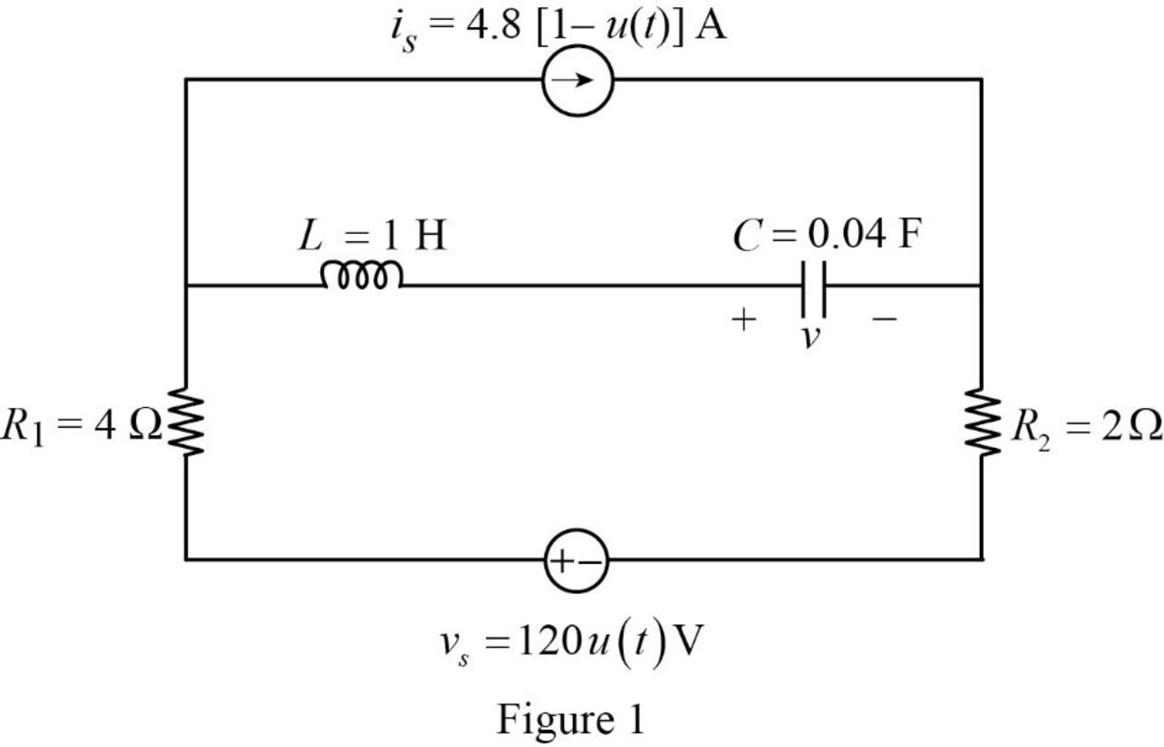
For a DC circuit, at steady state condition when time
The value of current source is calculated as follows:
The value of voltage source is calculated as follows:
Since the value of voltage source is zero it is short circuited.
Now, the Figure 1 is reduced as shown in Figure 2.
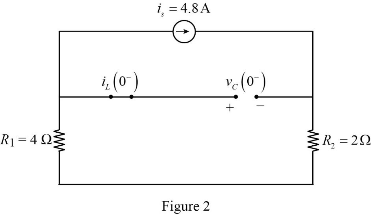
Refer to Figure 2, the capacitor is connected in parallel with the series connected resistors
Refer to Figure 2, since the capacitor is open circuited there is no current flow through the inductor.
The current through inductor and voltage across capacitor is always continuous so that,
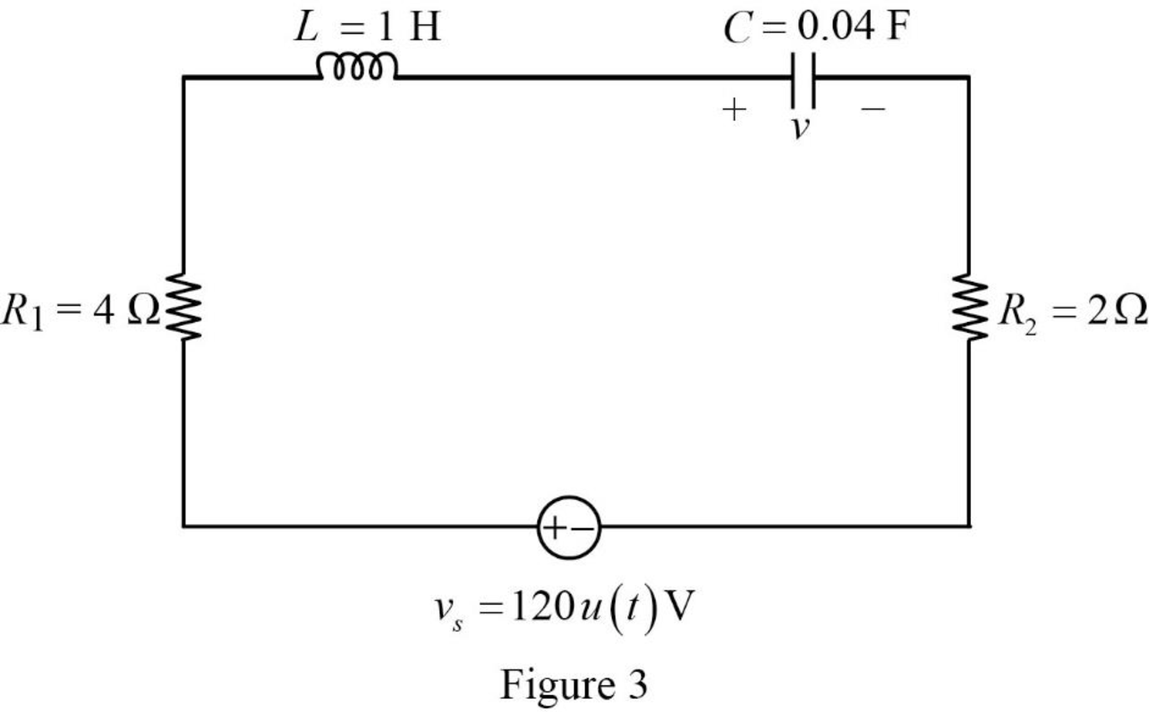
For time
The value of current source is calculated as follows:
Since the value of current source is zero it is open circuited.
Now, the Figure 1 is reduced as shown in Figure 3.
Substitute
Substitute
Substitute
Substitute
Apply Laplace transform for
Using element transformation methods with initial conditions convert the Figure 3 into s-domain.
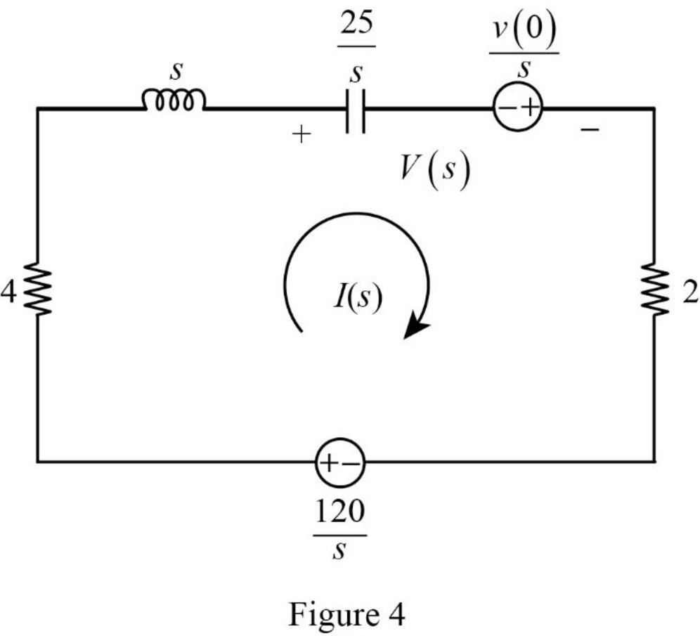
Apply Kirchhoff’s voltage law for the circuit shown in Figure 4.
Substitute
Simplify the above equation to find
From the equation (4), the characteristic equation is
Write a general expression to calculate the roots of quadratic equation
Comparing the equation (5) with the equation
Substitute
Simplify the above equation to find
Substitute the roots of characteristic equation in equation (4) to find
Refer to Figure 4, the voltage
Substitute
Assume,
Substitute equation (8) in equation (7).
Take partial fraction for equation (8).
The equation (10) can also be written as follows:
Simplify the above equation as follows:
Substitute
Simplify the above equation to find
Substitute
Simplify the above equation to find
Substitute
Simplify the above equation to find
Substitute
Substitute
Apply inverse Laplace transform for above equation to find
Simplify the above equation to find
Conclusion:
Thus, the expression of voltage
Want to see more full solutions like this?
Chapter 16 Solutions
Fundamentals of Electric Circuits


- b) The joint probability function for the random variables X and Y is given in Table below. Find a) the marginal probability function of X and Y. P(Y/X) and P(X/Y). c) P(X ≥ 2, Y ≤ 2) y 1 2 3 10.05 0.05 0.1 P(X, Y) = X 20.05 0.1 0.35 3 0 0.2 0.1arrow_forwardSuppose a random variable X as pmf / Px (x) = { %, x = 1, 2, 3, 0, otherwise. find constand c ①P(X = 1), P(X 7,2), PC1 3) C CDFarrow_forwardSuppose that a coin is tossed three so that the sample space is Let X represent the number of heads that can come up. i) Find the probability function corresponding to the random variable X. Assuming that the coin is fair ii) Find the distribution function for the random variable X. iii) Obtain its graph.arrow_forward
- Q9 A single-phase transformer, 2500 / 250 V, 50 kVA, 50 Hz has the following parameters, the Primary and secondary resistances are 0.8 ohm and 0.012 ohm respectively, the primary and secondary reactance are 4 ohm and 0.04 ohm respectively and the transformer gives 96% maximum efficiency at 75% full-load. The magnetizing component of-load current is 1.2 A on 2500 V side. 1- Draw the equivalent circuit referred to primary (H.V side) and inserts all the values in it 2- Find out Ammeter, voltmeter and wattmeter readings on open-circuit and short-circuit test. If supply is given to 2500 V side in both cases. Ans. O.C. Test (Vo= 2500 V, lo=1.24 A, Wo=781.25 w) S.C. Test (Vsc =164.924 V, Isc =20 A, Wsc =800 w )arrow_forwardQ2-A)- Enumerate the various losses in transformer. Explain how each loss varies with (Load current, supply voltage). B)- Draw the pharos diagram at load on primary side.arrow_forwardQ2- What are the parameters and loss that can be determined during open-circuit test of singlephase transformer. Draw the circuit diagram of open-circuit test and explain how can you calculate the Parameters and loss.arrow_forward
- Q2-Drive the condition of maximum efficiency of single-phase transformer. Q1- A 5 KVA, 500/250 V ,50 Hz, single phase transformer gave the following reading: O.C. Test: 250 V,2 A, 50 W (H.V. side open) S.C. Test: 25 V10 A, 60 W (L.V. side shorted) Determine: i) The efficiency on full load, 0.8 lagging p.f. ii) Draw the equivalent circuit referred to primary and insert all the values it.arrow_forwardQ2- Describe various losses in transformer. Explain how each loss varies with load current, supply voltagearrow_forwardQ1-A 12 KVA, 440/ 220 V, 50 Hz single phase transformer has 275 secondary turns. The no load current of transformer is 2A at power factor 0.375 when connected to 220 V, 50 Hz supply. The full load copper loss is 198.3 watt. Calculate a) Maximum value of flux in the core. b) Maximum efficiency at 0.8 lagging p.f c) KVA supply at maximum efficiencyarrow_forward
- Q1- A 5 KVA, 240/120 volt, single-phase transformer supplies rated current to a load at 120 V. Determine the magnitude of the load impedance as seen from the input terminals of the transformer. Ans. 11.52arrow_forwardQ1- A single phase transformer consumes 2 A on no load at p.f. 0.208 lagging. The turns ratio is 2/1 (step down). If the loads on the secondary is 25 A at a p.f. 0.866 lagging. Find the primary current and power factor.arrow_forwardI am seeking ideas or references regarding the auxiliary power output for a trolley. I’ve encountered difficulties finding information online about the power output for lights, buzzers, and speakers. Specifically, I am interested in the following questions: How many lights, buzzers, and speakers can a trolley approximately 48 feet in length accommodate?How can I determine their rated power?Any guidance or resources you can provide would be greatly appreciated. Thank you!arrow_forward
 Introductory Circuit Analysis (13th Edition)Electrical EngineeringISBN:9780133923605Author:Robert L. BoylestadPublisher:PEARSON
 Delmar's Standard Textbook Of ElectricityElectrical EngineeringISBN:9781337900348Author:Stephen L. HermanPublisher:Cengage Learning
 Programmable Logic ControllersElectrical EngineeringISBN:9780073373843Author:Frank D. PetruzellaPublisher:McGraw-Hill Education
 Fundamentals of Electric CircuitsElectrical EngineeringISBN:9780078028229Author:Charles K Alexander, Matthew SadikuPublisher:McGraw-Hill Education
 Electric Circuits. (11th Edition)Electrical EngineeringISBN:9780134746968Author:James W. Nilsson, Susan RiedelPublisher:PEARSON
 Engineering ElectromagneticsElectrical EngineeringISBN:9780078028151Author:Hayt, William H. (william Hart), Jr, BUCK, John A.Publisher:Mcgraw-hill Education,