In Prob. 15.201, the speed of point B is known to be constant. For the position shown, determine (a) the angular acceleration of the guide arm, (b) the acceleration of point C.
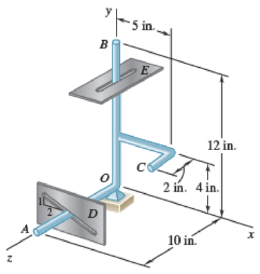
15.201 Several rods are brazed together to form the robotic guide arm shown that is attached to a ball-and-socket joint at O. Rod OA slides in a straight inclined slot, while rod OB slides in a slot parallel to the z axis. Knowing that at the instant shown vB = (9 in./s)k, determine (a) the angular velocity of the guide arm, (b) the velocity of point A, (c) the velocity of point C.

Fig. P15.201
(a)
The angular acceleration of the guide arm.
Answer to Problem 15.202P
The angular acceleration of the guide arm is
Explanation of Solution
Given information:
The velocity
Calculation:
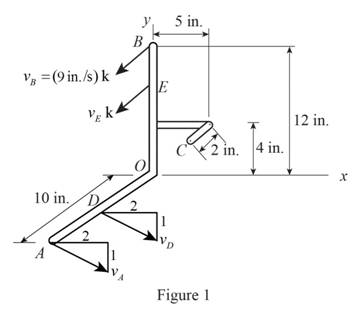
Sketch the Free Body Diagram of the robotic guide arm as shown in Figure 1.

Refer to Figure 1.
The velocity at D along the x axis is
The velocity at A along the x axis is
Calculate the position vector
The position of A.
The position of B.
The position of C.
Consider the angular velocity
Consider the velocity at A
Calculate the angular velocity of each plane using the relation of
Substitute
Resolving i, j and k components.
For i component.
For k component.
Calculate the angular velocity of each plane using the relation of
Substitute
Substitute
Resolving i, j and k components.
For i component.
For j component.
For k component.
Calculate the velocity at A
Substitute
Calculate the angular velocity along y direction
Substitute
Calculate the angular velocity
Substitute
Calculate the velocity of point A
Substitute
Calculate the velocity of point C
Substitute
Consider the angular acceleration
Consider the acceleration at A
Consider the acceleration at B
Calculate the angular acceleration at B of each plane using the relation of
Substitute
Resolving i, j and k components.
For i component.
For j component.
For k component.
Calculate the angular acceleration at A of each plane using the relation of
Substitute
Substitute 0 for
Resolving i, j and k components.
For i component.
For j component.
For k component.
Refer to Figure 1.
The acceleration at A along the x axis
Substitute
Calculate the angular acceleration along y axis
Substitute
Calculate the angular acceleration
Substitute
Therefore, the angular acceleration of the guide arm is
(b)
Find the acceleration of point C.
Answer to Problem 15.202P
The acceleration of point C is
Explanation of Solution
Given information:
The velocity at B is
Calculation:
Refer to part (a).
The angular velocity of the guide arm is
The angular acceleration of the guide arm is
The velocity at C is
Calculate the acceleration at C
Substitute
Therefore, the acceleration of point C is
Want to see more full solutions like this?
Chapter 15 Solutions
Vector Mechanics for Engineers: Statics and Dynamics
Additional Engineering Textbook Solutions
Java: An Introduction to Problem Solving and Programming (8th Edition)
Thermodynamics: An Engineering Approach
SURVEY OF OPERATING SYSTEMS
Automotive Technology: Principles, Diagnosis, And Service (6th Edition) (halderman Automotive Series)
Thinking Like an Engineer: An Active Learning Approach (4th Edition)
Starting Out with Python (4th Edition)
- Auto Controls DONT COPY ANSWERS Perform the partial fraction expansion of the following transfer function and find the impulse response: G(s) = (s/2 + 5/3) / (s^2 + 4s + 6) G(s) =( 6s^2 + 50) / (s+3)(s^2 +4)arrow_forwardDerive the Laplace transform of the following functions. Use the definition of Laplace transform. f(t)=sin4t and f(t)=cos2t Auto Controlsarrow_forwardhelparrow_forward
- any help i dont understandarrow_forwardBattery operated train Mueh Groll CD Af Pair 160,000 kg 0.0005 0.15 19 5m² 1.2kg/m³ 0.98 0.9 Tet neng 0.88 Tesla Prated Tesla Trated Ywheel ng Joyle 2 270 kW 440NM 0,45m 20 8.5kg m Consider a drive cycle of a 500km trip with 3 stops in the middle. Other than the acceleration and deceleration associated with the three stops, the tran maintains. constant cruise speed velocity of 324 km/hr. The tran will fast charge at each stop for 15 min at a rate Peharge = 350 kW Εμ (MN 15MIN Stop w charging (350kW) GMIJ t 6MM 6AW 1) calculate the battery power required to mantain. constant velocity of 324km/hr 2) determine the battery energy, energy required to constant velocity portion of this drive. Cover the 3) calculate the battery energy required to accelerate the train to 324/04/hr. 4) calculate the battery energy that is either fost in deceleration or recovered due to regenerative breaking etcarrow_forwardA 22-lb block B rests as shown on a 28-lb bracket A. The coefficients of friction are μs=0.30μs=0.30 and μk=0.25μk=0.25 between block B and bracket A, and there is no friction in the pulley or between the bracket and the horizontal surface. solved in a previous part. max weight of block C if block B is not to slide on bracket A is 5.045 lbs. Please solve for the acceleration of each Blockarrow_forward
- Test 1 .DOCX * A File Edit View Tools Help INDUSTRIAL ENGINEERING PROGRAMME IMB 411-INDUSTRIAL LOGISTICS TEST 1- SEPTEMBER 12, 2012 Instructions: Answer all questions. Time allowed is 1.5 hours. Identify your script with your student number ONLY (Do not write your name). 1. Define the following terms (i) Logistics management (ii) Supply chain management (iii) Vertical integration in a supply chain (3 Marks) (3 Marks) (3 Marks) 2. (a) Using examples of your choice, briefly discuss the following levels of customer service (1) Pre-transaction elements (ii) Transaction elements (4 Marks) (4 Marks) (iii) Post-transaction elements (4 Marks) (b) "The challenge facing Dumelang Enterprise (Pty) Ltd is to establish the real profitability of their customers and to develop service strategies that will improve the profitability of all customers". As a logistics consultant, briefly discuss how you can advise Dumelang's customer service management. 3. (a) List the three main forms of inventory in a…arrow_forwardIt is decided to install several single-jet Pelton wheels to produce a total power of 18 MW. The available head is 246 m. The wheel rotational speed is 650 rpm and the speed ratio (❤) = 0.46. The diameter of the nozzle (jet) is limited to be 0.167 m with a Cv of 0.95. The efficiency of each turbine is 87%. Determine: (1) The number of Pelton wheels to be used, and (2) The bucket angle.arrow_forwardPlease show All work and fill it in thermodynamicsarrow_forward
- Quick solution required. My request, Don't use Ai. Mechanical engineeringarrow_forwardPlease give handwritten solution, don't use chatgpt. Fbd should be includedarrow_forward(I) [40 Points] Using centered finite difference approximations as done in class, solve the equation for O: d20 dx² + 0.010+ Q=0 subject to the boundary conditions shown in the stencil below. Do this for two values of Q: (a) Q = 0.3, and (b) Q= √(0.5 + 2x)e-sinx (cos(5x)+x-0.5√1.006-x| + e −43*|1+.001+x* | * sin (1.5 − x) + (cosx+0.001 + ex-1250+ sin (1-0.9x)|) * x - 4.68x4. For Case (a) (that is, Q = 0.3), use the stencil in Fig. 1. For Case (b), calculate with both the stencils in Fig. 1 and Fig 2. For all the three cases, show a table as well as a plot of O versus x. Discuss your results. Use MATLAB and hand in the MATLAB codes. 1 0=0 x=0 2 3 4 0=1 x=1 Fig 1 1 2 3 4 5 6 7 8 9 10 11 0=0 x=0 0=1 x=1 Fig 2arrow_forward
 Elements Of ElectromagneticsMechanical EngineeringISBN:9780190698614Author:Sadiku, Matthew N. O.Publisher:Oxford University Press
 Mechanics of Materials (10th Edition)Mechanical EngineeringISBN:9780134319650Author:Russell C. HibbelerPublisher:PEARSON
 Thermodynamics: An Engineering ApproachMechanical EngineeringISBN:9781259822674Author:Yunus A. Cengel Dr., Michael A. BolesPublisher:McGraw-Hill Education
 Control Systems EngineeringMechanical EngineeringISBN:9781118170519Author:Norman S. NisePublisher:WILEY
 Mechanics of Materials (MindTap Course List)Mechanical EngineeringISBN:9781337093347Author:Barry J. Goodno, James M. GerePublisher:Cengage Learning
 Engineering Mechanics: StaticsMechanical EngineeringISBN:9781118807330Author:James L. Meriam, L. G. Kraige, J. N. BoltonPublisher:WILEY


