
Vector Mechanics For Engineers
12th Edition
ISBN: 9781259977237
Author: BEER
Publisher: MCG
expand_more
expand_more
format_list_bulleted
Concept explainers
Videos
Textbook Question
Chapter 15.4, Problem 15.120P
Knowing that crank AB rotates about point A with a constant angular velocity of 900 rpm clockwise, determine the acceleration of the piston P when
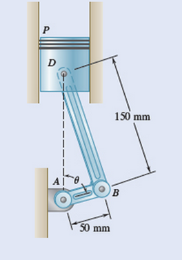
Fig. P15.120 and P15.121
Expert Solution & Answer
Want to see the full answer?
Check out a sample textbook solution
Students have asked these similar questions
=
The frame shown is fitted with three 50 cm diameter
frictionless pulleys. A force of F = 630 N is applied to the
rope at an angle ◊ 43°. Member ABCD is attached to the
wall by a fixed support at A. Find the forces indicated below.
Note: The rope is tangent to the pully (D) and not secured at
the 3 o'clock position.
a
b
•C
*су
G
E
e
d
BY NC SA
2013 Michael Swanbom
Values for dimensions on the figure are given in the following
table. Note the figure may not be to scale.
Variable Value
a
81 cm
b
50 cm
с
59 cm
d
155 cm
For all answers, take x as positive to the right and
positive upward.
At point A, the fixed support exerts a force of:
A
=
+
ĴN
and a reaction couple of:
→>
ΜΑ
Member CG is in Select an answer
magnitude
У
as
k N-m.
and carries a force of
N.
The lower jaw AB [Purple 1] and the upper jaw-handle AD
[Yellow 2] exert vertical clamping forces on the object at R.
The hand squeezes the upper jaw-handle AD [2] and the
lower handle BC [Orane 4] with forces F. (Member CD [Red 3]
acts as if it is pinned at D, but, in a real vise-grips, its
position is actually adjustable.) The clamping force, R,
depends on the geometry and on the squeezing force F
applied to the handles. Determine the proportionality
between the clamping force, R, and the squeezing force F for
the dimensions given.
d3
d4
R
1
B
d1
2
d2
D...
d5
F
4
F
Values for dimensions on the figure are given in the following
table. Note the figure may not be to scale.
Variable
Value
d1
65 mm
d2
156 mm
d3
50 mm
45
d4
d5
113 mm
30 mm
R =
F
A triangular distributed load of max intensity w =460 N/m
acts on beam AB. The beam is supported by a pin at A and
member CD, which is connected by pins at C and D
respectively. Determine the reaction forces at A and C.
Enter your answers in Cartesian components. Assume the
masses of both beam AB and member CD are negligible.
cc 040
BY NC SA
2016 Eric Davishahl
W
A
C
D
-a-
B
Ул
-b-
x
Values for dimensions on the figure are given in the following
table. Note the figure may not be to scale.
Variable Value
α
5.4 m
b
8.64 m
C
3.24 m
The reaction at A is A =
i+
ĴN.
λ =
i+
Ĵ N.
The reaction at C is C =
Chapter 15 Solutions
Vector Mechanics For Engineers
Ch. 15.1 - A rectangular plate swings from arms of equal...Ch. 15.1 - Knowing that wheel A rotates with a constant...Ch. 15.1 - The brake drum is attached to a larger flywheel...Ch. 15.1 - The motion of an oscillation flvdee1 is defined by...Ch. 15.1 - The motion of an oscillation flywheel is defined...Ch. 15.1 - Prob. 15.4PCh. 15.1 - A small grinding wheel is attached to the shaft of...Ch. 15.1 - A connecting rod is supported by a knife-edge at...Ch. 15.1 - When studying whiplash resulting from rear-end...Ch. 15.1 - The angular acceleration of an oscillating disk is...
Ch. 15.1 - The angular acceleration of a shaft is defined by...Ch. 15.1 - Prob. 15.10PCh. 15.1 - Prob. 15.11PCh. 15.1 - The rectangular block shown rotates about the...Ch. 15.1 - The rectangular block shown rotates about the...Ch. 15.1 - A circular plate of 120-mm radius is supported by...Ch. 15.1 - In Prob. 15.14, determine the velocity and...Ch. 15.1 - The earth makes one complete revolution around the...Ch. 15.1 - The earth makes one complete revolution on its...Ch. 15.1 - The sprocket wheel and chain shown initially at...Ch. 15.1 - Prob. 15.19PCh. 15.1 - The belt sander shown is initially at rest. If the...Ch. 15.1 - The rated speed of drum B of the belt sander shown...Ch. 15.1 - The two pulleys shown may be operated with the V...Ch. 15.1 - A cyclist uses a statior.ary trainer during the...Ch. 15.1 - gear reduction system consists of three gears A,...Ch. 15.1 - A belt is pulled to the right between cylinders A...Ch. 15.1 - Ring C has an inside radius of 55 mm and an...Ch. 15.1 - At the instant shown, the angular velocity of...Ch. 15.1 - A plastic film moves over two drums. During a 4-s...Ch. 15.1 - Cylinder A is moving downward with a velocity of 3...Ch. 15.1 - The system shown is held at rest by the...Ch. 15.1 - A load is to be raised 20 ft by the hoisting...Ch. 15.1 - A simple friction drive consists of two disks A...Ch. 15.1 - Two friction wheels A and B are both rotating...Ch. 15.1 - Two friction disks A and B are to be brought into...Ch. 15.1 - Two friction disks A and B are brought into...Ch. 15.1 - Steel tape is being wound onto a spool that...Ch. 15.1 - Prob. 15.37PCh. 15.2 - The ball rolls without slipping on the fixed...Ch. 15.2 - Three uniform rods—ABC, DCE, and FGH—are connected...Ch. 15.2 - An automobile travel, to the right at a constant...Ch. 15.2 - Prob. 15.39PCh. 15.2 - A painter is halfway up a 10-m ladder when the...Ch. 15.2 - Rod AB can slide freely along the floor and the...Ch. 15.2 - Rod AB can slide freely along the floor and the...Ch. 15.2 - Rod AB moves over a small wheel at C while end A...Ch. 15.2 - The disk shown moves in the xy plane. Knowing that...Ch. 15.2 - The disk shown moves in the xy p1ane. Knowing that...Ch. 15.2 - Prob. 15.46PCh. 15.2 - Velocity sensors are placed on a satellite that is...Ch. 15.2 - In the planetary gear system shown, the radius of...Ch. 15.2 - In the planetary gear system shown, the radius of...Ch. 15.2 - The outer gear C rotates with an angular velocity...Ch. 15.2 - In the simplified sketch of a ball bearing shown,...Ch. 15.2 - A simplified gear system for a mechanical watch is...Ch. 15.2 - Arm ACB rotates about point C with an angular...Ch. 15.2 - Arm ACB rotates about point C with an angular...Ch. 15.2 - Knowing that at the instant shown the angular...Ch. 15.2 - Prob. 15.56PCh. 15.2 - Knowing that the disk has a constant angular...Ch. 15.2 - The disk has a constant angular velocity of 20...Ch. 15.2 - The test rig is shown was developed to perform...Ch. 15.2 - In the concentric shown, a disk of 2-in. radius...Ch. 15.2 - In the engine system shown, l=160mmandb=60mm ....Ch. 15.2 - In the engine system shown, l=160 mm and b=60 mm....Ch. 15.2 - Knowing that the angular velocity of rod DE is a...Ch. 15.2 - In the position shown bar AB has an anu1ar...Ch. 15.2 - Linkage DBEF is part of a windshield wiper...Ch. 15.2 - Roberts linkage is named after Richard Roberts...Ch. 15.2 - Roberts linkage is named after Richard Roberts...Ch. 15.2 - For the oil pump rig shown, link AB causes the...Ch. 15.2 - For the oil pump rig shown, link AB causes the...Ch. 15.2 - Both 6-in.-radius wheels roll without slipping on...Ch. 15.2 - The 80-mm-radius wheel shown rolls to the left...Ch. 15.2 - For the gearing shown, derive an expression for...Ch. 15.3 - The disk rolls without sliding on the fixed...Ch. 15.3 - Bar BDE is pinned to two links, AB and CD. At the...Ch. 15.3 - A juggling club is thrown vertically into the air....Ch. 15.3 - At the instant shown during deceleration, the...Ch. 15.3 - A helicopter moves horizontally in the x direction...Ch. 15.3 - A 60-mm-radius drum is rigidly attached to a...Ch. 15.3 - Prob. 15.77PCh. 15.3 - In order to uncoil electrical wire from a...Ch. 15.3 - In order to uncoil electrical wire from a spool...Ch. 15.3 - The arm ABC rotates with an angular velocity of 4...Ch. 15.3 - The double gear rolls on the stationary left rack...Ch. 15.3 - An overhead door is guided by wheels at A and B...Ch. 15.3 - Rod ABD is guided by wheels at A and B that roll...Ch. 15.3 - Knowing that at the instant shown the angular...Ch. 15.3 - Prob. 15.85PCh. 15.3 - A motor at O drives the windshield wiper mechanism...Ch. 15.3 - A motor at O drives the windshield wiper mechanism...Ch. 15.3 - Rod AB can slide freely along the floor and the...Ch. 15.3 - Small wheels have been attached to the ends of bar...Ch. 15.3 - Two slots have been cut in plate FG and the plate...Ch. 15.3 - The disk is released from rest and rolls down the...Ch. 15.3 - The pin at B is attached to member ABD and can...Ch. 15.3 - Two identical rods ABF and DBE are Connected by a...Ch. 15.3 - Ann ABD is connected by pins to a collar at B and...Ch. 15.3 - Two rods ABD and DE are Connected to three collars...Ch. 15.3 - Two 500-mm rods are pin-connected at D as shown....Ch. 15.3 - At the instant shown, the velocity of collar A is...Ch. 15.3 - Prob. 15.98PCh. 15.3 - Describe the space centrode and the body centrode...Ch. 15.3 - Describe the space centrode and the body centrode...Ch. 15.3 - Using the method of Sec. 15.3, solve Prob. 15.60.Ch. 15.3 - Using the method of Sec. 15.3, solve Prob. 15.64.Ch. 15.3 - Using the method of Sec. 15.3, solve Prob. 15.65.Ch. 15.3 - Using the method of Sec. 15.3, solve Prob. 15.38.Ch. 15.4 - A rear-wheel-drive car starts from rest and...Ch. 15.4 - A 5-m steel beam is lowered by means of two cables...Ch. 15.4 - For a 5-m steel beam AE, the acceleration of point...Ch. 15.4 - A 900-mm rod rests on a horizontal table A force P...Ch. 15.4 - In Prob. 15.107, determine the point of the rod...Ch. 15.4 - Knowing that point A is moving to the right at a...Ch. 15.4 - Knowing that at the instant shown crank BC has a...Ch. 15.4 - automobile travels to the left at a constant speed...Ch. 15.4 - The 18-in.-radius flywheel is rigidly attached to...Ch. 15.4 - A 3-in.-radius drum is rigidly attached to a...Ch. 15.4 - A 3-in.-radius drum is rigidly attached to a...Ch. 15.4 - A heavy crate is being moved a sbo1 distance using...Ch. 15.4 - A wheel rolls without slipping on a fixed...Ch. 15.4 - The 100-nun-radius drum rolls without slipping on...Ch. 15.4 - In the planetary gear system shown, the radius of...Ch. 15.4 - The 200-mm-radius disk rolls without sliding on...Ch. 15.4 - Knowing that crank AB rotates about point A with a...Ch. 15.4 - Knowing that crank AB rotates about point A with a...Ch. 15.4 - In the two-cylinder air compressor shown, the...Ch. 15.4 - Prob. 15.123PCh. 15.4 - Arm AB has a constant angular velocity of 16 rad/s...Ch. 15.4 - Arm AB has a constant angular velocity of 16 rad/s...Ch. 15.4 - A straight rack rests on a gear of radius r=3 in....Ch. 15.4 - The elliptical exercise machine has fixed axes of...Ch. 15.4 - The elliptical exercise machine has fixed axes of...Ch. 15.4 - Prob. 15.129PCh. 15.4 - Knowing that at the instant shown bar DE has an...Ch. 15.4 - Knowing that at the instant shown bar AB has a...Ch. 15.4 - Prob. 15.132PCh. 15.4 - Prob. 15.133PCh. 15.4 - Prob. 15.134PCh. 15.4 - Roberts linkage is named after Richard Roberts...Ch. 15.4 - For the oil pump rig shown, link AB causes the...Ch. 15.4 - Denoting by rA the position vector of a point A of...Ch. 15.4 - The drive disk of the Scotch crosshead mechanism...Ch. 15.4 - The wheels attached to the ends of rod AB roll...Ch. 15.4 - The wheels attached to the ends of rod AB roll...Ch. 15.4 - A disk of radius r rolls to the right with a...Ch. 15.4 - Ladder AB moves over a smooth corner at C while...Ch. 15.4 - Prob. 15.143PCh. 15.4 - Crank4B rotates with a constant c1ockise angular...Ch. 15.4 - Crank 4B rotates with a constant clockwise angular...Ch. 15.4 - Solve the engine system from Sample Prob. 15.15...Ch. 15.4 - The position of rod AB is controlled by a disk of...Ch. 15.4 - A wheel of radius r rolls without slipping along...Ch. 15.4 - In Prob. 15. 148, show that the path of P is a...Ch. 15.5 - A person walks radially inward on a platform that...Ch. 15.5 - Prob. 15.150PCh. 15.5 - Prob. 15.151PCh. 15.5 - Two rotating rods are connected by slider block P....Ch. 15.5 - Two rotating rods are connected by slider block P....Ch. 15.5 - Pin P is attached to the wheel shown and slides in...Ch. 15.5 - Knowing that at the instant shown the angular...Ch. 15.5 - Knowing that at the instant shown the anu1ar...Ch. 15.5 - The motion of pin P is guided by slots cut in...Ch. 15.5 - Four pins slide in four separate slots cut in a...Ch. 15.5 - Solve Prob. 15.158, assuming that the plate...Ch. 15.5 - The cage of a mine elevator moves downward at a...Ch. 15.5 - Prob. 15.161PCh. 15.5 - A rocket sled is tested o a straight track that is...Ch. 15.5 - Prob. 15.163PCh. 15.5 - Prob. 15.164PCh. 15.5 - Prob. 15.165PCh. 15.5 - In the automated welding setup shown, the position...Ch. 15.5 - In the automated welding setup shown, the position...Ch. 15.5 - A chain is looped around two gears of radius 40 mm...Ch. 15.5 - A chain is looped around two gears of radius 40 mm...Ch. 15.5 - Prob. 15.170PCh. 15.5 - The human leg can be crudely approximated as two...Ch. 15.5 - The collar P slides outward at a constant relative...Ch. 15.5 - Pin P slides in a circular slot cut in the plate...Ch. 15.5 - Rod AD is bent in the shape of an are of a circle...Ch. 15.5 - Solve Prob. 15.l74 when =90 .Ch. 15.5 - Prob. 15.176PCh. 15.5 - Prob. 15.177PCh. 15.5 - In Prob. 15.177, determine the angular velocity...Ch. 15.5 - Prob. 15.179PCh. 15.5 - Prob. 15.180PCh. 15.5 - Rod AB passes through a collar that is welded to...Ch. 15.5 - Solve Prob. 15.181 assuming block A moves to the...Ch. 15.5 - In Prob. 15.157, determine the acceleration of pin...Ch. 15.6 - The bowling ball shown rolls without slipping on...Ch. 15.6 - The bowling ball shown rolls without slipping on...Ch. 15.6 - Prob. 15.186PCh. 15.6 - At the instant considered, the radar antenna shown...Ch. 15.6 - Prob. 15.188PCh. 15.6 - The disk of a portable sander rotates at the...Ch. 15.6 - Prob. 15.190PCh. 15.6 - Prob. 15.191PCh. 15.6 - In the system shown, disk A is free to rotate...Ch. 15.6 - Prob. 15.193PCh. 15.6 - A radar system is used to track a new experimental...Ch. 15.6 - Prob. 15.195PCh. 15.6 - A 3-in-radius disk spins at the constant rate 2=4...Ch. 15.6 - The cone shown rolls on the zx plane with its apex...Ch. 15.6 - At the instant shown, the robotic arm ABC is being...Ch. 15.6 - Prob. 15.199PCh. 15.6 - In Prob. 15.199, determine (a) the common angular...Ch. 15.6 - Several rods are brazed together to form the...Ch. 15.6 - In Prob. 15.201, the speed of point B is known to...Ch. 15.6 - Rod AB of length 25 in. is connected by ball...Ch. 15.6 - Rod AB has a length of 13 in. and is connected by...Ch. 15.6 - Rod BC and BD are each 840 mm long and are...Ch. 15.6 - Rod AB is connected by ball-and-socket joints to...Ch. 15.6 - Rod AB of length 29 in. is connected by...Ch. 15.6 - Rod AB of length 300 mm is connected by ball...Ch. 15.6 - Rod AB of length 300 mm is connected by...Ch. 15.6 - Two shafts AC and EG, which lie in the vertical yz...Ch. 15.6 - Solve Prob. 15.210, assuming that the arm of the...Ch. 15.6 - Rod BC has a length of 42 in. and is connected by...Ch. 15.6 - Rod AB has a length of 275 mm and is connected by...Ch. 15.6 - For the mechanism of Prob.15.204, determine the...Ch. 15.6 - In Prob. 15.205, determine the acceleration of...Ch. 15.6 - In Prob. 15.206, determine the acceleration of...Ch. 15.6 - In Prob. 15.207, determine the acceleration of...Ch. 15.6 - In Prob. 15.208, determine the acceleration of...Ch. 15.6 - In Prob. 15.209, determine the acceleration of...Ch. 15.7 - A flight simulator is used to train pilots on how...Ch. 15.7 - A flight simulator is used to train pilots on how...Ch. 15.7 - Prob. 15.222PCh. 15.7 - Prob. 15.223PCh. 15.7 - Rod AB is welded to the 0.3-m-radius plate that...Ch. 15.7 - The bent rod shown rotates at the constant rate of...Ch. 15.7 - The bent pipe shown rotates at the constant rate...Ch. 15.7 - The circular plate shown rotates about its...Ch. 15.7 - Manufactured items are spray-painted as they pass...Ch. 15.7 - Solve Prob. 15.227, assuming that at the instant...Ch. 15.7 - Solve Prob. 15.225, assuming that at the instant...Ch. 15.7 - Using the method of Sec. 15.7A, solve Prob....Ch. 15.7 - Using the method of Sec. 15.7A, solve Prob....Ch. 15.7 - Using the method of Sec. 15.7A, solve Prob....Ch. 15.7 - The 400-mm bar AB is made to rotate at the...Ch. 15.7 - The 400-mm bar AB is made to rotate at the rate...Ch. 15.7 - The arm AB of length 16 ft is used to provide an...Ch. 15.7 - The remote manipulator system (RMS) shown is used...Ch. 15.7 - A disk with a radius of 120 mm rotates at the...Ch. 15.7 - The crane shown rotates at the constant rate...Ch. 15.7 - Prob. 15.240PCh. 15.7 - Prob. 15.241PCh. 15.7 - Prob. 15.242PCh. 15.7 - Prob. 15.243PCh. 15.7 - A square plate of side 2r is welded to a vertical...Ch. 15.7 - Two disks, each of 130-mm radius, are welded to...Ch. 15.7 - In Prob. 15.245, determine the velocity and...Ch. 15.7 - The position of the stylus tip A is controlled by...Ch. 15 - A wheel moves in the xy plane in such a way that...Ch. 15 - Two blocks and a pulley e connected by...Ch. 15 - A baseball pitching machine is designed to deliver...Ch. 15 - The flywheel OD on the elliptical machine analyzed...Ch. 15 - Prob. 15.252RPCh. 15 - Knowing that at the instant shown rod AB has zero...Ch. 15 - Rod AB is attached to a collar at A and is fitted...Ch. 15 - flows through a curved pipe .AB that rotates with...Ch. 15 - A disk of 0.15-m radius rotates at the constant...Ch. 15 - Two rods AE and BD pass through holes drilled into...Ch. 15 - Rod BC of length 24 in. is connected by ball...Ch. 15 - In the positions shown, the thin rod moves at a...
Knowledge Booster


Learn more about
Need a deep-dive on the concept behind this application? Look no further. Learn more about this topic, mechanical-engineering and related others by exploring similar questions and additional content below.Similar questions
- 56 Clamps like the one shown are commonly used in woodworking applications. This clamp has the dimensions given in the table below the figure, and its jaws are mm thick (in the direction perpendicular to the plane of the picture). a.) The screws of the clamp are adjusted so that there is a uniform pressure of P = 150 kPa being applied to the workpieces by the jaws. Determine the force carried in each screw. Hint: the uniform pressure can be modeled in 2-D as a uniform distributed load with intensity w = Pt (units of N/m) acting over the length of contact between the jaw and the workpiece. b.) Determine the minimum vertical force (parallel to the jaws) required to pull either one of the workpieces out of the clamp jaws. Use a coefficient of static friction between all contacting surfaces of μs = 0.56 and the same clamping pressure given for part (a). 2013 Michael Swanbom A B C a Values for dimensions on the figure are given in the following table. Note the figure may not be to scale.…arrow_forwardDetermine the force in each member of the space truss given F=5 kN. Use positive to indicate tension and negative to indicate compression. F E Z -2 m. B 3 m C 5 m 3 m A -4 m. AB = KN FAC = FAD = KN KN KN FBC = KN FBD FBE = = KN Farrow_forwardA short brass cyclinder (denisty=8530 kg/m^3, cp=0.389 kJ/kgK, k=110 W/mK, and alpha=3.39*10^-5 m^2/s) of diameter 4 cm and height 20 cm is initially at uniform temperature of 150 degrees C. The cylinder is now placed in atmospheric air at 20 degrees C, where heat transfer takes place by convection with a heat transfer coefficent of 40 W/m^2K. Calculate (a) the center temp of the cylinder, (b) the center temp of the top surface of the cylinder, and (c) the total heat transfer from the cylinder 15 min after the start of the cooling. Solve this problem using the analytical one term approximation method. (Answer: (a) 45.7C, (b)45.3C, (c)87.2 kJ)arrow_forward
- A short brass cyclinder (denisty=8530 kg/m^3, cp=0.389 kJ/kgK, k=110 W/mK, and alpha=3.39*10^-5 m^2/s) of diameter 4 cm and height 20 cm is initially at uniform temperature of 150 degrees C. The cylinder is now placed in atmospheric air at 20 degrees C, where heat transfer takes place by convection with a heat transfer coefficent of 40 W/m^2K. Calculate (a) the center temp of the cylinder, (b) the center temp of the top surface of the cylinder, and (c) the total heat transfer from the cylinder 15 min after the start of the cooling. Solve this problem using the analytical one term approximation method.arrow_forwardA 6 cm high rectangular ice block (k=2.22 W/mK, and alpha=0.124*10^-7 m^2/s) initially at -18 degrees C is placed on a table on its square base 4 cm by 4cm in size in a room at 18 degrees C. The heat transfer coefficent on the exposed surfaces of the ice block is 12 W/m^2K. Disregarding any heat transfer from the base to the table, determine how long it will be before the ice block starts melting. Where on the ice block will the first liquid droplets appear? Solve this problem using the analytical one-term approximation method.arrow_forwardConsider a piece of steel undergoing a decarburization process at 925 degrees C. the mass diffusivity of carbon in steel at 925 degrees C is 1*10^-7 cm^2/s. Determine the depth below the surface of the steel at which the concentration of carbon is reduced to 40 percent from its initial value as a result of the decarburization process for (a) an hour and (b) 10 hours. Assume the concnetration of carbon at the surface is zero throughout the decarburization process.arrow_forward
- Please do not rely too much on chatgpt, because its answer may be wrong. Please consider it carefully and give your own answer. You can borrow ideas from gpt, but please do not believe its answer.Very very grateful! Please do not copy other's work,i will be very very grateful!!arrow_forwardMultiple Choice Circle the best answer to each statement. 1. Which geometry attribute deviation(s) can be limited with a profile of a surface tolerance? A. Location B. Orientation C. Form D. All of the above 2. A true profile may be defined with: A. Basic radii B. Basic angles C. Formulas D. All of the above 3. Which modifier may be applied to the profile tolerance value? A B C. D. All of the above 4. The default tolerance zone for a profile tolerance is: A. Non-uniform B. Unilateral C. Bilateral equal distribution D. Bilateral-unequal distribution 5. An advantage of using a profile tolerance in place of a coordinate tolerance is: A. A bonus tolerance is permitted. B. A datum feature sequence may be specified C. A profile tolerance always controls size D. All of the above 6. The shape of the tolerance zone for a profile tolerance is: A. Two parallel planes B. The same as the true profile of the toleranced surface C. Equal bilateral D. Cylindrical when the diameter symbol is speci- fied…arrow_forwardOne thousand kg/h of a (50-50 wt%) acetone-in-water solution is to be extracted at 25C in a continuous, countercurrent system with pure 1,1,2-trichloroethane to obtain a raffinate containing 10 wt% acetone. Using the following equilibrium data, determine with an equilateral-triangle diagram: a- the minimum flow rate of solvent; b- the number of stages required for a solvent rate equal to 1.5 times minimum, and composition of each streamleaving each stage. c- Repeat the calculation of (a) and (b) if the solvent used has purity 93wt% (4wr% acetone, 3wt% water impurities) acetone water 1,1,2-trichloroethane Raffinate. Weight Extract. Weight 0.6 0.13 0.27 Fraction Acetone Fraction Acetone 0.5 0.04 0.46 0.44 0.56 0.4 0.03 0.57 0.29 0.40 0.3 0.02 0.68 0.12 0.18 0.2 0.015 0.785 0.0 0.0 0.1 0.01 0.89 0.55 0.35 0.1 0.5 0.43 0.07 0.4 0.57 0.03 0.3 0.68 0.02 0.2 0.79 0.01 0.1 0.895 0.005arrow_forward
- 2500 kg/hr of (20-80) nicotine water solution is to be extracted with benzene containing 0.5% nicotine in the 1st and 2ed stages while the 3rd stage is free of nicotine. Cross- current operation is used with different amounts of solvent for each stages 2000kg/hr in the 1st stage, 2300 kg/hr in the 2nd stage, 2600 kg/hr in the 3rd, determine: - a- The final raffinate concentration and % extraction. b- b- The minimum amount of solvent required for counter-current operation if the minimum concentration will be reduced to 5% in the outlet raffinate. Equilibrium data Wt % Nicotine in water Wt % Nicotine in benzene 0 4 16 25 0 4 21 30arrow_forwardQuiz/An eccentrically loaded bracket is welded to the support as shown in Figure below. The load is static. The weld size for weld w1 is h1=6mm, for w2 h2 5mm, and for w3 is h3 -5.5 mm. Determine the safety factor (S.f) for the welds. F=22 kN. Use an AWS Electrode type (E90xx). 140 101.15 REDMI NOTE 8 PRO AI QUAD CAMERA Farrow_forward(read image)arrow_forward
arrow_back_ios
SEE MORE QUESTIONS
arrow_forward_ios
Recommended textbooks for you
 Elements Of ElectromagneticsMechanical EngineeringISBN:9780190698614Author:Sadiku, Matthew N. O.Publisher:Oxford University Press
 Mechanics of Materials (10th Edition)Mechanical EngineeringISBN:9780134319650Author:Russell C. HibbelerPublisher:PEARSON
 Thermodynamics: An Engineering ApproachMechanical EngineeringISBN:9781259822674Author:Yunus A. Cengel Dr., Michael A. BolesPublisher:McGraw-Hill Education
 Control Systems EngineeringMechanical EngineeringISBN:9781118170519Author:Norman S. NisePublisher:WILEY
 Mechanics of Materials (MindTap Course List)Mechanical EngineeringISBN:9781337093347Author:Barry J. Goodno, James M. GerePublisher:Cengage Learning
 Engineering Mechanics: StaticsMechanical EngineeringISBN:9781118807330Author:James L. Meriam, L. G. Kraige, J. N. BoltonPublisher:WILEY
Elements Of Electromagnetics
Mechanical Engineering
ISBN:9780190698614
Author:Sadiku, Matthew N. O.
Publisher:Oxford University Press
Mechanics of Materials (10th Edition)
Mechanical Engineering
ISBN:9780134319650
Author:Russell C. Hibbeler
Publisher:PEARSON
Thermodynamics: An Engineering Approach
Mechanical Engineering
ISBN:9781259822674
Author:Yunus A. Cengel Dr., Michael A. Boles
Publisher:McGraw-Hill Education
Control Systems Engineering
Mechanical Engineering
ISBN:9781118170519
Author:Norman S. Nise
Publisher:WILEY
Mechanics of Materials (MindTap Course List)
Mechanical Engineering
ISBN:9781337093347
Author:Barry J. Goodno, James M. Gere
Publisher:Cengage Learning
Engineering Mechanics: Statics
Mechanical Engineering
ISBN:9781118807330
Author:James L. Meriam, L. G. Kraige, J. N. Bolton
Publisher:WILEY
Dynamics - Lesson 1: Introduction and Constant Acceleration Equations; Author: Jeff Hanson;https://www.youtube.com/watch?v=7aMiZ3b0Ieg;License: Standard YouTube License, CC-BY