
Concept explainers
Videos
Examine the filter for the circuit in Fig. 15.69. (a) Without going through a full mathematical analysis of the circuit, determine what kind of filter this is. (b) Determine an expression for the transfer function H(s) = vout/vin. (c) Use MATLAB to construct a Bode plot (with frequency in Hz) for R1 = R2 = 10 kΩ, C1 = 159 nF, C2 = 1.59 nF.
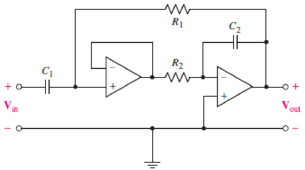
■ FIGURE 15.69
Want to see the full answer?
Check out a sample textbook solution
Chapter 15 Solutions
ENGINEERING CIRCUIT...(LL)>CUSTOM PKG.<
Additional Engineering Textbook Solutions
Vector Mechanics for Engineers: Statics
SURVEY OF OPERATING SYSTEMS
Java: An Introduction to Problem Solving and Programming (8th Edition)
Starting Out with Programming Logic and Design (5th Edition) (What's New in Computer Science)
Web Development and Design Foundations with HTML5 (8th Edition)
Automotive Technology: Principles, Diagnosis, And Service (6th Edition) (halderman Automotive Series)


- Q6 The FET shown in Fig. 1.43 has gm = 3.4 mS and rd =100 K. Find the approximate lower cutoff frequency. Ans: 735.1 Hz. 25V 1.5ΜΩ 20 ΚΩ 0.02µF HH 2ΚΩ 0.02µF HH 330kQ 820 ΩΣ 1.0µF www 40ΚΩarrow_forwardThe solution is with a pen and paper, without artificial intelligence.arrow_forwardQ5 For the network of Fig. 1.42; determine re, Avmid, Zi, Avsmid, and the low cutoff frequency. Ans: 30.23 2; 0.983; 21.13 KS; 0.955; 193.16 Hz. 14V + Vs 1 ΚΩ 0.1 µF Vi 120 ΚΩ B-100 0.1 µF o Vo 30 ΚΩ 32.2 ΚΩ 18.2 ΚΩ Fig. 1.42 Circuit for Q5. 31arrow_forward
- Q1) (a) State Biot-Savart's law (b) The y- and z-axes, respectively, carry filamentary currents 10 A along ay and 20 A along -az. Find H at (- 3, 4, 5).arrow_forwardQ5) a) State Ampere's circuit law. b) In a certain conducting region, H = yz(x² + y²)ax - y²xzay + 4x²y²a, A/m. (a) Determine J at (5, 2, -3) (b) Find the current passing through x = -1, 0 < y, z <2 (c) Show that V⚫H=0arrow_forwardFig. 1.43 Circuit for Q6- Q7 For the network of Fig. 1.44: a-Determine fH; and fHo b- Find fg and fr. c- Sketch the frequency response for the high-frequency region using a Bode plot and determine the cutoff frequency. Ans: 277.89 KHz; 2.73 MHz; 895.56 KHz; 107.47 MHz. 14V Cw=5pF Cbc-12 pF Cwo-8pF Che=40. pF 5.6kQ C-8pF 68kQ 0.47µF ww 0.82 kQ V₁ 0.47uF AN B=120 3.3kQ 10ΚΩ 1.2k0 =20µF Fig. 1.44 Circuit for Q7.arrow_forward
- Q3) An infinite long filamentary wire carries a current of 2A in the +z direction. calculate: (a)B at (-3,4,7) (b) the flux through the square loop described by 25 16,0 Sz≤4, 0=90°.arrow_forwardQ3) An infinitely long conductor is bent into an L shape as shown in Figure below. If a direct current of 5 A flows in the current, find the magnetic field intensity at (2, 2, 0). 5 A 5 Aarrow_forwardEx. 1° let Ĥ = -y (x²+y^³) ax + x (x²+y"`) ây":" H 5 find J M total current Passing through Z=oplane with the rectangular -\-2<<2arrow_forward
- Q) Given the magnetic field vector potential: A= y² za, +2(x+1)y z ay- (x+1) z² az (A/m), find: (1)magnetic flux density B, (2)magnetic field intensity H, (3) current density J and (4) the current passing through surface y = 1,0≤x≤1, 0 ≤z≤1.arrow_forwardQ9 For the network of Fig. 1.46: a- Determine gmo and gm. b- Find A, and Ay, in the mid-frequency range. c- Determine fH; and fHo Ans: 3.33 mS; 1.91 mS; -4.39; -4.27; 1.84 MHz; 3.68 MHz. + 1.5 kQ 20V 3220ΚΩ 1µF 68kQ AN CwF4pF Co=8 pF Cwo=6pF Cgs=12pF 53.9ΚΩ Cds=3pF 6.8µF o Vo Dss=10mA Vp=-6V 15.6 ΚΩ 2.2k =10µF Fiarrow_forwardQs For the network of Fig. 1.45: a- Determine fH, and fHo b- Find fp and fr c- Sketch the frequency response for the high-frequency region using a Bode plot and determine the cutoff frequency. Ans: 2.87 MHz, 185.78 MHz, 1.05 MHz, 105 MHz. 14V CWF8pF Cwo-10pF Cbc-20 pF Cbe=30pF 120 ΚΩ Co=12pF 1 ΚΩ B-100 0.1 µF Vs 0.1 HF Z; Vo www 30 kQ 2.2 ΚΩ € 8.2 kQ Fig. 1.45 Circuit for Carrow_forward
 Introductory Circuit Analysis (13th Edition)Electrical EngineeringISBN:9780133923605Author:Robert L. BoylestadPublisher:PEARSON
 Delmar's Standard Textbook Of ElectricityElectrical EngineeringISBN:9781337900348Author:Stephen L. HermanPublisher:Cengage Learning
 Programmable Logic ControllersElectrical EngineeringISBN:9780073373843Author:Frank D. PetruzellaPublisher:McGraw-Hill Education
 Fundamentals of Electric CircuitsElectrical EngineeringISBN:9780078028229Author:Charles K Alexander, Matthew SadikuPublisher:McGraw-Hill Education
 Electric Circuits. (11th Edition)Electrical EngineeringISBN:9780134746968Author:James W. Nilsson, Susan RiedelPublisher:PEARSON
 Engineering ElectromagneticsElectrical EngineeringISBN:9780078028151Author:Hayt, William H. (william Hart), Jr, BUCK, John A.Publisher:Mcgraw-hill Education,