
(a)
Find the value of
(a)
Answer to Problem 16E
The value of
Explanation of Solution
Given data:
Refer to Figure 15.53 in the textbook.
Formula used:
Write the expression to calculate the impedance of the passive elements resistor, inductor and capacitor in s-domain.
Here,
Calculation:
Given that the output voltage should be taken across the inductor in series RLC circuit.
Generally, the transfer function of the series RLC circuit for which the output is taken across the inductor is,
The modified circuit of given circuit is drawn as Figure 1.
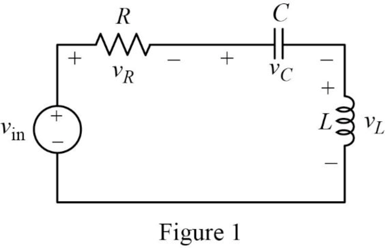
The Figure 1 is redrawn as impedance circuit in s-domain in Figure 2 using the equations (1), (2) and (3).
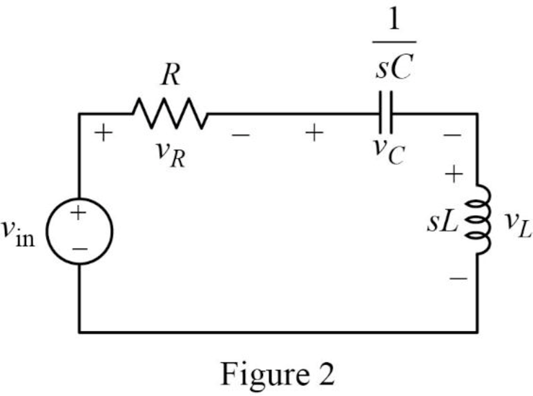
Write the general expression to calculate the transfer function of the circuit in Figure 2.
Here,
Apply Kirchhoff’s voltage law on Figure 2 to find
Rearrange the above equation to find
Substitute
Compare the above equation with the equation (4) to obtain the following values.
Rearrange the equation (6).
Rearrange the above equation to find
Rearrange the equation (7) to find
Substitute
Conclusion:
Thus, the value of
(b)
Find the values of inductor
(b)
Answer to Problem 16E
The value of inductor
Explanation of Solution
Given data:
The value of the resistor
The value of the resonant frequency
Calculation:
Case (i):
From part (a),
Substitute
Rearrange the above equation to find
Rearrange the above equation to find
Rearrange the equation (9).
Rearrange the above equation to find
Substitute
Rearrange the above equation to find
Take square root on both sides of the above equation to find
Substitute
Case (ii):
Substitute
Rearrange the above equation to find
Rearrange the above equation to find
Substitute
Rearrange the above equation to find
Take square root on both sides of the above equation to find
Substitute
Case (iii):
Substitute
Rearrange the above equation to find
Rearrange the above equation to find
Substitute
Rearrange the above equation to find
Take square root on both sides of the above equation to find
Substitute
Conclusion:
Thus, the value of inductor
(c)
Construct the magnitude Bode plots for the three cases
(c)
Explanation of Solution
Calculation:
Simplify the equation (4) to find
Case (i):
Substitute
Case (ii):
Substitute
Case (iii):
Substitute
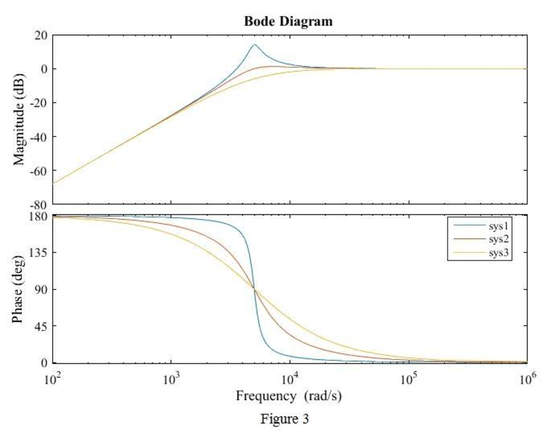
The equations (15), (16) and (17) are the transfer function of the given series RLC circuit at three different cases
The MATLAB code is given below to sketch the magnitude Bode plots for the three cases using the equations (15), (16) and (17).
MATLAB Code:
clc;
clear all;
close all;
sys1=tf([1 0 0],[1 1000 (25*10^6)]);
sys2=tf([1 0 0],[1 5000 (25*10^6)]);
sys3=tf([1 0 0],[1 10000 (25*10^6)]);
bode(sys1,sys2,sys3)
legend({'sys1','sys2','sys3'},'Location','best')
Output:
The MATLAB output is shown in Figure 3.
Conclusion:
Thus, the magnitude Bode plot for the three cases
Want to see more full solutions like this?
Chapter 15 Solutions
ENGINEERING CIRCUIT...(LL)>CUSTOM PKG.<

- V₁(t) ww ZRI ZLI ZL2 ZTH Zci VTH Zc21 Figure 8. Circuit diagram showing calculation approach for VTH and Z TH we want to create a blackbox for the red region, we want to use the same input signal conditions as previously the design of your interference ector circuit: Sine wave with a 1 Vpp, with a frequency of 100 kHz (interference) Square wave with 2.4Vpp, with a frequency of 10 kHz (signal) member an AC Thevenin equivalent is only valid at one frequency. We have chosen to calculate the Thevenin equivalent circuit (and therefore the ackbox) at the interference frequency (i.e. 100 kHz), and the signal frequency (i.e. 10 kHz) as these are the key frequencies to analyse. Your boss is assured you that the waveform converter module has been pre-optimised to the DAB Receiver if you use the recommended circuit topology.arrow_forwardVs(t) + v(t) + vi(t) ZR ZL Figure 1: Second order RLC circuit Zc + ve(t) You are requested to design the circuit shown in Figure 1. The circuit is assumed to be operating at its resonant frequency when it is fed by a sinusoidal voltage source Vs (t) = 2sin(le6t). To help design your circuit you have been given the value of inductive reactance ZL = j1000. Assume that the amplitude of the current at resonance is Is (t) = 2 mA. Based on this information, answer the following to help design your circuit. Use cartesian notation for your answers, where required.arrow_forwardWhat is the attenuation at the resonant frequency? You should use the LTSpice cursors for your measurement. Answer to within 1% accuracy, or enter 0, or infinity (as "inf") (a) Attenuation (dB) = dB Check You may have noticed that it was significantly easier to use frequency-domain "AC" simulation to measure the attenuation, compared to the steps we performed in the last few questions. (i.e. via a time-domain "transient" simulation). AC analysis allows us to observe and quantify large scale positive or negative changes in a signal of interest across a wide range of different frequencies. From the response you will notice that only frequencies that are relatively close to 100 kHz have been attenuated. This is the result of the Band-reject filter you have designed, and shows the 'rejection' (aka attenuation) of any frequencies that lie in a given band. The obvious follow-up question is how do we define this band? We use a quantity known as the bandwidth. A commonly used measurement for…arrow_forward
- V₁(t) ww ZRI ZLI ZL2 ZTH Zci VTH Zc21 Figure 8. Circuit diagram showing calculation approach for VTH and Z TH we want to create a blackbox for the red region, we want to use the same input signal conditions as previously the design of your interference ector circuit: Sine wave with a 1 Vpp, with a frequency of 100 kHz (interference) Square wave with 2.4Vpp, with a frequency of 10 kHz (signal) member an AC Thevenin equivalent is only valid at one frequency. We have chosen to calculate the Thevenin equivalent circuit (and therefore the ackbox) at the interference frequency (i.e. 100 kHz), and the signal frequency (i.e. 10 kHz) as these are the key frequencies to analyse. Your boss is assured you that the waveform converter module has been pre-optimised to the DAB Receiver if you use the recommended circuit topology.arrow_forwardVs(t) + v(t) + vi(t) ZR ZL Figure 1: Second order RLC circuit Zc + ve(t) You are requested to design the circuit shown in Figure 1. The circuit is assumed to be operating at its resonant frequency when it is fed by a sinusoidal voltage source Vs (t) = 2sin(le6t). To help design your circuit you have been given the value of inductive reactance ZL = j1000. Assume that the amplitude of the current at resonance is Is (t) = 2 mA. Based on this information, answer the following to help design your circuit. Use cartesian notation for your answers, where required.arrow_forwardFor a band-rejection filter, the response drops below this half power point at two locations as visualised in Figure 7, we need to find these frequencies. Let's call the lower frequency-3dB point as fr and the higher frequency -3dB point fH. We can then find out the bandwidth as f=fHfL, as illustrated in Figure 7. 0dB Af -3 dB Figure 7. Band reject filter response diagram Considering your AC simulation frequency response and referring to Figure 7, measure the following from your AC simulation. 1% accuracy: (a) Upper-3db Frequency (fH) = Hz (b) Lower-3db Frequency (fL) = Hz (c) Bandwidth (Aƒ) = Hz (d) Quality Factor (Q) =arrow_forward
- V₁(t) ww ZRI ZLI Z12 Zci Zcz Figure 4. Notch filter circuit topology ши Consider the second order resonant circuit shown in Figure 4. Impedances ZLIZ C1. ZL2. Z c2 combine together forming a two-stage "band- reject" filter, so called because it rejects a "band" (aka range) of frequencies. This circuit topology is also commonly referred to as a "band-stop" filter or "notch" filter. The output of the DAB receiver block has been approximated via Thevenin's theorem for you as a voltage source Vs (t) and associated series impedance Z RI To succeed in our goal, we are going to use an iterative design approach. First we will design the interference rejector, and then repeat the process, using the output of the interference rejector to check the provided waveform converter works as intended.arrow_forward1. What is the settling time for your output signal (BRF_OUT)? For this question, We define the settling time as the period of time it has taken for the output to settle into a steady state - ie when your oscillation first decays (aka reduces) to less than approximately 1/20 (5%) of the initial value. (a) Settling timearrow_forward2. What is the total impedance Zt of your designed circuit? Represent your result in cartesian form NOTE: use j to represent sqare root Zt=arrow_forward
- An electric resistance space heater is designed such that it resembles a rectangular box 55 cm high, 75 cm long, and 20 cm wide filled with 45 kg of oil. The heater is to be placed against a wall, and thus heat transfer from its back surface is negligible. The surface temperature of the heater is not to exceed 75°C in a room at 25°C for safety considerations. The emissivity of the outer surface of the heater is 0.8 and the average temperature of the ceiling and wall surfaces is the same as the room air temperature. The properties of air at 1 atm and the film temperature are: k = 0.02753 W/m-°C, v=1.798 x 10⁻⁵ m²/s, Pr = 0.7228, and ẞ= 0.003096K-1 Wall T₁ =75°C Oil € = 0.8 Electric heater Heating element Disregarding heat transfer from the bottom and top surfaces of the heater in anticipation that the top surface will be used as a shelf, determine the power rating of the heater in W. The power rating of the heater is W.arrow_forwardcircuit 2arrow_forwardSuppose you have 8 LED's connected to port-B (Bo-B7) of PIC16F877A and one switch connected to port-D (Do) as shown in figure below. Write a program code that performs a nibble (4-bits) toggling: if the switch is released then LED's (Bo to B3) are OFF and LED's (B4 to B7) are ON, while if the switch is pressed then LED's (Bo to B3) are ON and LED's (B4 to B7) are OFF. Use 300ms delay for each case with 4MHz frequency. 13 14 22 NATHON 20 U1 OSC1/CLKIN U2 33 REOINT 20 34 OSC2/CLKOUT 19 RB1 35 3 18 RB2 RADIANO debt0RB3PGM 30 4 17 37 5 10 RA1/AN1 RB4 38 RA2/ANZ/VREF-/CVREF 15 RB5 39097 RA3/AN3VREF RB6/PGC 7 14 40 RA4/TOCK/C1OUT 13 RB7/PGO RAS/ANA/SS/CZOUT 15 RCO/T1OSO/TICKI 10 11 REQIANS/RD 18 RC1/T10S/CCP2 17 10 RE1/AN/WR REZ/ANTICS MCLR/Vpp/THV RC2/CCP1 LED-BARGRAPH-RED RC3/SCK/SCL RC4/SDUSDA RC5/SDO Eng of ROSTX/CX RC7/RX/DT RDO/PSPO RD1/PSP1 RD2PSP2 RO3/PSP3 RD4/PSP4 ROS/PSP5 RD6/PSP6 RD7/PSP7 PIC16F877A +5V R1 100Rarrow_forward
 Introductory Circuit Analysis (13th Edition)Electrical EngineeringISBN:9780133923605Author:Robert L. BoylestadPublisher:PEARSON
 Delmar's Standard Textbook Of ElectricityElectrical EngineeringISBN:9781337900348Author:Stephen L. HermanPublisher:Cengage Learning
 Programmable Logic ControllersElectrical EngineeringISBN:9780073373843Author:Frank D. PetruzellaPublisher:McGraw-Hill Education
 Fundamentals of Electric CircuitsElectrical EngineeringISBN:9780078028229Author:Charles K Alexander, Matthew SadikuPublisher:McGraw-Hill Education
 Electric Circuits. (11th Edition)Electrical EngineeringISBN:9780134746968Author:James W. Nilsson, Susan RiedelPublisher:PEARSON
 Engineering ElectromagneticsElectrical EngineeringISBN:9780078028151Author:Hayt, William H. (william Hart), Jr, BUCK, John A.Publisher:Mcgraw-hill Education,