
ENGINEERING CIRCUIT...(LL)>CUSTOM PKG.<
9th Edition
ISBN: 9781260540666
Author: Hayt
Publisher: MCG CUSTOM
expand_more
expand_more
format_list_bulleted
Videos
Textbook Question
Chapter 15, Problem 4E
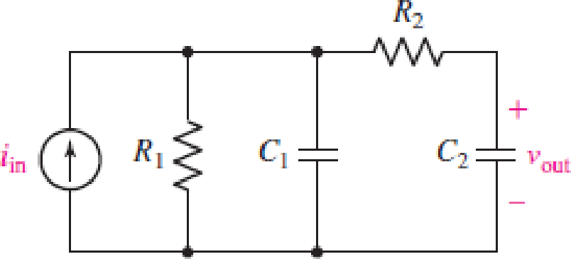
For the circuit in Fig. 15.54, (a) derive an algebraic expression for the transfer function H(jω) = vout/iin terms of circuit components R1, R2, C1, and C2; and (b) evaluate the magnitude of H at frequencies of 100 Hz, 10 kHz, and 1 MHz for case where R1 = 20 kΩ, R2 = 5 kΩ, C1 = 10 nF, and C2 = 40 nF.
FIGURE 15.54
Expert Solution & Answer
Want to see the full answer?
Check out a sample textbook solution
Students have asked these similar questions
Can you solve the following problem and show how the answer was found:
A17)
Using Carson's rule, determine the transmission bandwidth for commercial FM radio broadcasting, provided that the maximum value of frequency deviation is 75 kHz and the bandwidth of the audio signal is 15 kHz
Chapter 15 Solutions
ENGINEERING CIRCUIT...(LL)>CUSTOM PKG.<
Ch. 15.1 - Write an expression for the transfer function of...Ch. 15.2 - Calculate HdB at = 146 rad/s if H(s) equals (a)...Ch. 15.2 - Prob. 3PCh. 15.2 - Draw the Bode phase plot for the transfer function...Ch. 15.2 - Construct a Bode magnitude plot for H(s) equal to...Ch. 15.2 - Draw the Bode phase plot for H(s) equal to (a)...Ch. 15.2 - Prob. 7PCh. 15.3 - A parallel resonant circuit is composed of the...Ch. 15.3 - Prob. 9PCh. 15.4 - A marginally high-Q parallel resonant circuit has...
Ch. 15.5 - A series resonant circuit has a bandwidth of 100...Ch. 15.6 - Referring to the circuit of Fig. 15.25a, let R1 =...Ch. 15.6 - Prob. 13PCh. 15.6 - Prob. 14PCh. 15.6 - The series combination of 10 and 10 nF is in...Ch. 15.7 - A parallel resonant circuit is defined by C = 0.01...Ch. 15.8 - Design a high-pass filter with a cutoff frequency...Ch. 15.8 - Design a bandpass filter with a low-frequency...Ch. 15.8 - Design a low-pass filter circuit with a gain of 30...Ch. 15 - For the RL circuit in Fig. 15.52, (a) determine...Ch. 15 - For the RL circuit in Fig. 15.52, switch the...Ch. 15 - Examine the series RLC circuit in Fig. 15.53, with...Ch. 15 - For the circuit in Fig. 15.54, (a) derive an...Ch. 15 - For the circuit in Fig. 15.55, (a) derive an...Ch. 15 - For the circuit in Fig. 15.56, (a) determine the...Ch. 15 - For the circuit in Fig. 15.57, (a) determine the...Ch. 15 - Sketch the Bode magnitude and phase plots for the...Ch. 15 - Use the Bode approach to sketch the magnitude of...Ch. 15 - If a particular network is described by transfer...Ch. 15 - Use MATLAB to plot the magnitude and phase Bode...Ch. 15 - Determine the Bode magnitude plot for the...Ch. 15 - Determine the Bode magnitude and phase plot for...Ch. 15 - Prob. 15ECh. 15 - Prob. 16ECh. 15 - For the circuit of Fig. 15.56, construct a...Ch. 15 - Construct a magnitude and phase Bode plot for the...Ch. 15 - For the circuit in Fig. 15.54, use LTspice to...Ch. 15 - For the circuit in Fig. 15.55, use LTspice to...Ch. 15 - Prob. 21ECh. 15 - A certain parallel RLC circuit is built using...Ch. 15 - A parallel RLC network is constructed using R = 5...Ch. 15 - Prob. 24ECh. 15 - Delete the 2 resistor in the network of Fig....Ch. 15 - Delete the 1 resistor in the network of Fig....Ch. 15 - Prob. 28ECh. 15 - Prob. 29ECh. 15 - Prob. 30ECh. 15 - A parallel RLC network is constructed with a 200 H...Ch. 15 - Prob. 32ECh. 15 - A parallel RLC circuit is constructed such that it...Ch. 15 - Prob. 34ECh. 15 - Prob. 35ECh. 15 - An RLC circuit is constructed using R = 5 , L = 20...Ch. 15 - Prob. 37ECh. 15 - Prob. 38ECh. 15 - For the network of Fig. 15.25a, R1 = 100 , R2 =...Ch. 15 - Assuming an operating frequency of 200 rad/s, find...Ch. 15 - Prob. 41ECh. 15 - Prob. 42ECh. 15 - For the circuit shown in Fig. 15.64, the voltage...Ch. 15 - Prob. 44ECh. 15 - Prob. 45ECh. 15 - Prob. 46ECh. 15 - The filter shown in Fig. 15.66a has the response...Ch. 15 - Prob. 48ECh. 15 - Examine the filter for the circuit in Fig. 15.68....Ch. 15 - Examine the filter for the circuit in Fig. 15.69....Ch. 15 - (a)Design a high-pass filter with a corner...Ch. 15 - (a) Design a low-pass filter with a break...Ch. 15 - Prob. 53ECh. 15 - Prob. 54ECh. 15 - Design a low-pass filter characterized by a...Ch. 15 - Prob. 56ECh. 15 - The circuit in Fig. 15.70 is known as a notch...Ch. 15 - (a) Design a two-stage op amp filter circuit with...Ch. 15 - Design a circuit which removes the entire audio...Ch. 15 - Prob. 61ECh. 15 - If a high-pass filter is required having gain of 6...Ch. 15 - (a) Design a second-order high-pass Butterworth...Ch. 15 - Design a fourth-order high-pass Butterworth filter...Ch. 15 - (a) Design a Sallen-Key low-pass filter with a...Ch. 15 - (a) Design a Sallen-Key low-pass filter with a...Ch. 15 - A piezoelectric sensor has an equivalent circuit...Ch. 15 - Design a parallel resonant circuit for an AM radio...Ch. 15 - The network of Fig. 15.72 was implemented as a...Ch. 15 - Determine the effect of component tolerance on the...
Additional Engineering Textbook Solutions
Find more solutions based on key concepts
CONCEPT QUESTIONS
15.CQ3 The ball rolls without slipping on the fixed surface as shown. What is the direction ...
Vector Mechanics for Engineers: Statics and Dynamics
The job of the _____ is to fetch instructions, carry out the operations commanded by the instructions, and prod...
Starting Out With Visual Basic (8th Edition)
What types of coolant are used in vehicles?
Automotive Technology: Principles, Diagnosis, And Service (6th Edition) (halderman Automotive Series)
This optional Google account security feature sends you a message with a code that you must enter, in addition ...
SURVEY OF OPERATING SYSTEMS
How does a computers main memory differ from its auxiliary memory?
Java: An Introduction to Problem Solving and Programming (8th Edition)
What is an uninitialized variable?
Starting Out with Programming Logic and Design (5th Edition) (What's New in Computer Science)
Knowledge Booster


Learn more about
Need a deep-dive on the concept behind this application? Look no further. Learn more about this topic, electrical-engineering and related others by exploring similar questions and additional content below.Similar questions
- 2. Laboratory Preliminary Discussion First-order High-pass RC Filter Analysis The first-order high-pass RC filter shown in figure 3 below represents all voltages and currents in the time domain. We will again convert the circuit to its s-domain equivalent as shown in figure 4 and apply Laplace transform techniques. ic(t) C vs(t) i₁(t) + + vc(t) R1 ww Vi(t) || 12(t) V2(t) R₂ Vout(t) VR2(t) = V2(t) Figure 3: A first-order high-pass RC filter represented in the time domain. Ic(s) C + Vs(s) I₁(s) + + Vc(s) R₁ www V₁(s) 12(s) V₂(s) R₂ Vout(S) = VR2(S) = V2(s) Figure 4: A first-order high-pass RC filter represented in the s-domain. Again, to generate the s-domain expression for the output voltage, You (S) = V2 (s), for the circuit shown in figure 4 above, we can apply voltage division in the s-domain as shown in equation 2 below. Equation 2 will be used in the prelab computations to find an expression for the output voltage, xc(t), in the time domain. equation (2) R₂ Vout(s) = V₂(s) = R₂+…arrow_forwardCan you show me the steps to get the last part after the second equal sign.arrow_forwardPrelab Information 1. Laboratory Preliminary Discussion First-order Low-pass RC Filter Analysis The first-order low-pass RC filter shown in figure 1 below represents all voltages and currents in the time domain. It is of course possible to solve for all circuit voltages using time domain differential equation techniques, but it is more efficient to convert the circuit to its s-domain equivalent as shown in figure 2 and apply Laplace transform techniques. vs(t) i₁(t) + R₁ ww V₁(t) 12(t) Lic(t) Vout(t) = V2(t) R₂ Vc(t) C Vc(t) VR2(t) = V2(t) + Vs(s) Figure 1: A first-order low-pass RC filter represented in the time domain. I₁(s) R1 W + V₁(s) V₂(s) 12(s) Ic(s) + Vout(S) == Vc(s) Vc(s) Zc(s) = = VR2(S) V2(s) Figure 2: A first-order low-pass RC filter represented in the s-domain.arrow_forward
- A.15 Consider a communication channel, transfer characteristic of which is defined by the nonlinear relation, y(t) = x(t) + x² (t), where x(t) is the input and y(t) is the output. Assuming the input is an FM signal, x(t) = cos (2лft+(t)), find y(t). Is it possible to retrieve x(t) from y(t)? If so, how?arrow_forward1) Show that a regenerative receiver can be used to recover message from the following modulated signals. a. DSB-PC b. DSB-SC 1b) Does the receiver need to recover the carrier phase? 1c) What are the filtering requirements and restrictions on message signal bandwidth and carrier frequency.arrow_forward2) Estimate the transmission bandwidth for the following FM modulated signals (W is the message bandwidth) a) W1KHz and frequency deviation of 75KHz b) W = 20KHz and frequency deviation of 75KHz c) W1KHz and frequency deviation of 150KHz d) W20KHz and frequency deviation of 150KHZarrow_forward
- I want to explain how the result becomes (735.1) Hz) and what are the steps and explain the reasons? Q6 The FET shown in Fig. 1.43 has gm = 3.4mS and ra =100 K. Find the approximate lower cutoff frequency. Ans: 735.1 Hz. 25V 2ΚΩ 1.5ΜΩ 0.02µF 0.02µF 20 ΚΩ 330kQ 820 ΩΣ OpF Fig. 1.43 Circuit for Q6. 40ΚΩarrow_forward3. What is the function of LM565 pin 6? 4. What is the purpose of the multistage low-pass filter between the LM565 output and the comparator input? C10.1μ FSK Input w₁ R2 100k -o+5V(Vcc) VR1 10k C4 C5: 0.1 μ. 0.1μ 0.1 μ 8 10 R3 R4 D₁ FSK Phase Rx 7 10K 10K Detector www ww ww 1N4004 + Demodulated Output 6 AMP R₁ 6 100k 3 C₂ 0.05 μ VCO 4 5 9 U1 -5V LM565 -0-5V(VEE) Fig. 14-2 FSK demodulator U2 R6 μ4741 10karrow_forward1. What components determine the free-running frequency of the VCO in LM565 of Fig. 14-2? 2. What is the purpose of μA741 in Fig. 14-2? C10.1μ FSK Input -o+5V(Vcc) VR1 10k C4 C5: 0.1 μ. 0.1 μ 0.1 μ 8 10 R3 R4 R5 Phase Rx 7 10K 10K 10k D₁ FSK Detector www ww ww ww 1N4004 + Demodulated Output AMP 6 R₁ 6 100k w₁ R2 100k 3 C₂ 0.05 μ VCO 4 5 9 U1 -5V LM565 -0-5V(VEE) Fig. 14-2 FSK demodulator U2 R6 μ4741 10karrow_forward
- When troubleshooting power and control circuits, approximate meter readings should be anticipated if the meter readings are going to be used to help determine circuit problems. Determine the expected DMM reading if the ciircuit is working properly. The expected reading of DMM 1 with the motor on is what VAC? And the expected reading of DMM 2 with the motor is on is what VAC? And The expected reading of DMM 3 with the motor on is What mA?arrow_forwardDU 1. Describe the operations of Q1, Q2 and LM566. 2. Describe the functions of VR1 and VR2. R6 lk R3 BRUD 3. If the input frequency is higher than the FSK frequency, does the FSK modulator operate normally? 0+12V R10 5.6k 6 10k VRI 500k U₁ LM566 3 VCO output 7 Digital input R₁ VR2 10k ww 1k Qi C945 C945 C5 I 0.1 uF C6 luF C₁ 0.01μ R2 10k ww R$ 100k C3 +12V 0.01μ R9 100k +12V 6 R710k Rs 100k 6 R4 100k P FSK output ww ww + www + 3 3 4 U U₂ 1000p -12V HA741 1000p-12V µА741 Fig. 13-2 FSK modulator CTS circuit.arrow_forward. 30-dB, right-circularly polarized antenna in a radio link radiates 5-W of power t 2 GHz. The input impedance of this antenna is 75 ohms, and it is attached ɔ a 50-ohm transmission line. The receiving antenna has an impedance mismatch at its terminals, - which leads to a VSWR of 2. The receiving antenna is about 95% efficient and has a field pattern near the beam maximum given by E, = (2âx + jây) F, (0, 0). The distance between the two antennas is 4,000 km, and the receiving antenna Directivity is 100. Determine the Minimum power Delivered to receiving antenna. 1arrow_forward
arrow_back_ios
SEE MORE QUESTIONS
arrow_forward_ios
Recommended textbooks for you
 Introductory Circuit Analysis (13th Edition)Electrical EngineeringISBN:9780133923605Author:Robert L. BoylestadPublisher:PEARSON
 Delmar's Standard Textbook Of ElectricityElectrical EngineeringISBN:9781337900348Author:Stephen L. HermanPublisher:Cengage Learning
 Programmable Logic ControllersElectrical EngineeringISBN:9780073373843Author:Frank D. PetruzellaPublisher:McGraw-Hill Education
 Fundamentals of Electric CircuitsElectrical EngineeringISBN:9780078028229Author:Charles K Alexander, Matthew SadikuPublisher:McGraw-Hill Education
 Electric Circuits. (11th Edition)Electrical EngineeringISBN:9780134746968Author:James W. Nilsson, Susan RiedelPublisher:PEARSON
 Engineering ElectromagneticsElectrical EngineeringISBN:9780078028151Author:Hayt, William H. (william Hart), Jr, BUCK, John A.Publisher:Mcgraw-hill Education,
Introductory Circuit Analysis (13th Edition)
Electrical Engineering
ISBN:9780133923605
Author:Robert L. Boylestad
Publisher:PEARSON
Delmar's Standard Textbook Of Electricity
Electrical Engineering
ISBN:9781337900348
Author:Stephen L. Herman
Publisher:Cengage Learning
Programmable Logic Controllers
Electrical Engineering
ISBN:9780073373843
Author:Frank D. Petruzella
Publisher:McGraw-Hill Education
Fundamentals of Electric Circuits
Electrical Engineering
ISBN:9780078028229
Author:Charles K Alexander, Matthew Sadiku
Publisher:McGraw-Hill Education
Electric Circuits. (11th Edition)
Electrical Engineering
ISBN:9780134746968
Author:James W. Nilsson, Susan Riedel
Publisher:PEARSON
Engineering Electromagnetics
Electrical Engineering
ISBN:9780078028151
Author:Hayt, William H. (william Hart), Jr, BUCK, John A.
Publisher:Mcgraw-hill Education,
David Sarnoff, Howard Armstrong & the Superheterodyne Receiver; Author: Kathy Loves Physics & History;https://www.youtube.com/watch?v=7eTfF67Ka5w;License: Standard Youtube License