
EBK MECHANICS OF MATERIALS
7th Edition
ISBN: 8220102804487
Author: BEER
Publisher: YUZU
expand_more
expand_more
format_list_bulleted
Concept explainers
Videos
Textbook Question
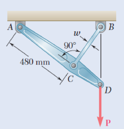
Chapter 1.5, Problem 39P
Link BC is 6 mm thick and is made of a steel with a 450-MPa ultimate strength in tension. What should be its width w if the structure shown is being designed to support a 20-kN load P with a factor of safety of 3?
Fig. P1.38 and P1.39
Expert Solution & Answer
Want to see the full answer?
Check out a sample textbook solution
Students have asked these similar questions
draw a kinematic diagram
Rigid bodies ENG2016. Full complete solutions need okk don't use guidelines but solve full accurate steps by steps don't use chat gpt or any other ai okkk just solve complete solutions okkk take your time but solve complete solutions
Question 6 I need to show all work step by step dynamics
Chapter 1 Solutions
EBK MECHANICS OF MATERIALS
Ch. 1.2 - Two solid cylindrical rods AB and BC are welded...Ch. 1.2 - Two solid cylindrical rods AB and BC are welded...Ch. 1.2 - Two solid cylindrical rods AB and BC are welded...Ch. 1.2 - Two solid cylindrical rods AB and BC are welded...Ch. 1.2 - A strain gage located at C on the surface of bone...Ch. 1.2 - Two brass rods AB and BC, each of uniform...Ch. 1.2 - Each of the four vertical links has an 8 36-mm...Ch. 1.2 - Link AC has a uniform rectangular cross section 18...Ch. 1.2 - Three forces, each of magnitude P = 4 kN, are...Ch. 1.2 - Link BD consists of a single bar 1 in. wide and 12...
Ch. 1.2 - For the Pratt bridge truss and loading shown,...Ch. 1.2 - The frame shown consists of four wooden members,...Ch. 1.2 - An aircraft tow bar is positioned by means of a...Ch. 1.2 - Two hydraulic cylinders are used to control the...Ch. 1.2 - Determine the diameter of the largest circular...Ch. 1.2 - Two wooden planks, each 12 in. thick and 9 in....Ch. 1.2 - When the force P reached 1600 lb, the wooden...Ch. 1.2 - A load P is applied to a steel rod supported as...Ch. 1.2 - The axial force in the column supporting the...Ch. 1.2 - Three wooden planks are fastened together by a...Ch. 1.2 - A 40-kN axial load is applied to a short wooden...Ch. 1.2 - An axial load P is supported by a short W8 40...Ch. 1.2 - Link AB, of width b = 2 in. and thickness t=14...Ch. 1.2 - Determine the largest load P that can be applied...Ch. 1.2 - Knowing that = 40 and P = 9 kN, determine (a) the...Ch. 1.2 - The hydraulic cylinder CF, which partially...Ch. 1.2 - For the assembly and loading of Prob. 1.7,...Ch. 1.2 - Two identical linkage-and-hydraulic-cylinder...Ch. 1.5 - Two wooden members of uniform rectangular cross...Ch. 1.5 - Two wooden members of uniform rectangular cross...Ch. 1.5 - The 1.4-kip load P is supported by two wooden...Ch. 1.5 - Two wooden members of uniform cross section are...Ch. 1.5 - A centric load P is applied to the granite block...Ch. 1.5 - A 240-kip load P is applied to the granite block...Ch. 1.5 - A steel pipe of 400-mm outer diameter is...Ch. 1.5 - A steel pipe of 400-mm outer diameter is...Ch. 1.5 - A steel loop ABCD of length 5 ft and of 38-in....Ch. 1.5 - Link BC is 6 mm thick, has a width w = 25 mm, and...Ch. 1.5 - Link BC is 6 mm thick and is made of a steel with...Ch. 1.5 - Members AB and BC of the truss shown are made of...Ch. 1.5 - Members AB and BC of the truss shown are made of...Ch. 1.5 - Link AB is to be made of a steel for which the...Ch. 1.5 - Two wooden members are joined by plywood splice...Ch. 1.5 - For the joint and loading of Prob. 1.43, determine...Ch. 1.5 - Three 34-in.-diameter steel bolts are to be used...Ch. 1.5 - Three steel bolts are to be used to attach the...Ch. 1.5 - A load P is supported as shown by a steel pin that...Ch. 1.5 - A load P is supported as shown by a steel pin that...Ch. 1.5 - A steel plate 14 in. thick is embedded in a...Ch. 1.5 - Determine the factor of safety for the cable...Ch. 1.5 - Link AC is made of a steel with a 65-ksi ultimate...Ch. 1.5 - Solve Prob. 1.51, assuming that the structure has...Ch. 1.5 - Each of the two vertical links CF connecting the...Ch. 1.5 - Solve Prob. 1.53, assuming that the pins at C and...Ch. 1.5 - In the structure shown, an 8-mm-diameter pin is...Ch. 1.5 - In an alternative design for the structure of...Ch. 1.5 - Prob. 57PCh. 1.5 - The Load and Resistance Factor Design method is to...Ch. 1 - In the marine crane shown, link CD is known to...Ch. 1 - Two horizontal 5-kip forces are applied to pin B...Ch. 1 - For the assembly and loading of Prob. 1.60,...Ch. 1 - Two steel plates are to be held together by means...Ch. 1 - A couple M of magnitude 1500 N m is applied to...Ch. 1 - Knowing that link DE is 18 in. thick and 1 in....Ch. 1 - A 58-in.-diameter steel rod AB is fitted to a...Ch. 1 - In the steel structure shown, a 6-mm-diameter pin...Ch. 1 - Prob. 67RPCh. 1 - A force P is applied as shown to a steel...Ch. 1 - The two portions of member AB are glued together...Ch. 1 - The two portions of member AB are glued together...
Knowledge Booster


Learn more about
Need a deep-dive on the concept behind this application? Look no further. Learn more about this topic, mechanical-engineering and related others by exploring similar questions and additional content below.Similar questions
- Qu. 3 The automobile is originally at rest s = 0. If it then starts to increase its speed at i = (0.05t2)ft/s?, where t is in seconds, determine the magnitudes of its velocity and acceleration at s = 550 ft. please show all work from dynamics step by step formulaarrow_forwardquestion 5 and 6 from dynamics I need to show all work step by step problemsarrow_forwardStudy Area Document Sharing User Settings Access Pearson mylabmastering.pearson.com P Pearson MyLab and Mastering The crash cushion for a highway barrier consists of a nest of barrels filled with an impact-absorbing material. The barrier stopping force is measured versus the vehicle penetration into the barrier. (Figure 1) Part A P Course Home b My Questions | bartleby Review Determine the distance a car having a weight of 4000 lb will penetrate the barrier if it is originally traveling at 55 ft/s when it strikes the first barrel. Express your answer to three significant figures and include the appropriate units. Figure 1 of 1 36 μΑ S = Value Units Submit Request Answer Provide Feedback ? Next >arrow_forward
- Water is the working fluid in an ideal Rankine cycle. Saturated vapor enters the turbine at 12 MPa, and the condenser pressure is 8 kPa. The mass flow rate of steam entering the turbine is 50 kg/s. Determine: (a) the net power developed, in kW. (b) the rate of heat transfer to the steam passing through the boiler, in kW. (c) the percent thermal efficiency. (d) the mass flow rate of condenser cooling water, in kg/s, if the cooling water undergoes a temperature increase of 18°C with negligible pressure change in passing through the condenser.arrow_forward4. The figure below shows a bent pipe with the external loading FA 228 lb, and M₁ = M₂ = 1 kip-ft. The force Fernal loading FA = 300 lb, FB: parallel to the y-axis, and and yc = 60°. = 125 lb, Fc = acts parallel to the x-z plane, the force FB acts Cartesian resultan Coordinate direction angles of Fc are ac = 120°, ẞc = 45°, a. Compute the resultant force vector of the given external loading and express it in EST form. b. Compute the resultant moment vector of the given external loading about the origin, O, and express it in Cartesian vector form. Use the vector method while computing the moments of forces. c. Compute the resultant moment vector of the given external loading about the line OA and express it in Cartesian vector form. :00 PM EST k ghoufran@buffaternal du 2 ft M₁ A 40° FA M2 C 18 in 1 ft Fc 25 houfran@bald.edu - Feb 19, 3 ft FBarrow_forwardThe differential equation of a cruise control system is provided by the following equation: Find the closed loop transfer function with respect to the reference velocity (vr) . a. Find the poles of the closed loop transfer function for different values of K. How does the poles move as you change K? b. Find the step response for different values of K and plot in MATLAB. What can you observe? c. For the given transfer function, find tp, ts, tr, Mp . Plot the resulting step response. G(s) = 40/(s^2 + 4s + 40)arrow_forward
- Auto Controls Perform the partial fraction expansion of the following transfer function and find the impulse response: G(s) = (s/2 + 5/3) / (s^2 + 4s + 6) G(s) =( 6s^2 + 50) / (s+3)(s^2 +4)arrow_forwardStudy Area Document Sharing User Settings mylabmastering.pearson.com Access Pearson P Pearson MyLab and Mastering The 150-lb skater passes point A with a speed of 6 ft/s. (Figure 1) Figure 1 of 1 Part A P Course Home b My Questions | bartleby Determine his speed when he reaches point B. Neglect friction. Express your answer to three significant figures and include the appropriate units. με ? VB = Value Units Submit Request Answer Part B Determine the normal force exerted on him by the track at this point. Express your answer to three significant figures and include the appropriate units. ☐ о Α NB = Value Units Submit Request Answer Provide Feedback ? ■Review Next >arrow_forwardmylabmastering.pearson.com Access Pearson P Pearson MyLab and Mastering P Course Home b My Questions | bartleby Study Area Document Sharing User Settings The 100-kg crate is subjected to the forces shown. The crate is originally at rest. The coefficient of kinetic friction between the crate and the surface is μk = 0.2. (Figure 1) Part A Determine the distance it slides in order to attain a speed of 8.1 m/s. Express your answer to three significant figures and include the appropriate units. Figure 500 N 1 of 1 Α S = Value Units Submit Request Answer Provide Feedback ? ■Review Next >arrow_forward
- The differential equation of a DC motor can be described by the following equation Find the transfer function between the applied voltage ( Va)and the motor speed (thetadot m). What is the steady state speed of the motor after a voltage (Va = 10V) has been applied. Find the transfer function between the applied voltage (Va) and the shaft angle (thetadot m) .arrow_forwardStudy Area Document Sharing User Settings Access Pearson mylabmastering.pearson.com P Pearson MyLab and Mastering The crash cushion for a highway barrier consists of a nest of barrels filled with an impact-absorbing material. The barrier stopping force is measured versus the vehicle penetration into the barrier. (Figure 1) Part A P Course Home b My Questions | bartleby Review Determine the distance a car having a weight of 4000 lb will penetrate the barrier if it is originally traveling at 55 ft/s when it strikes the first barrel. Express your answer to three significant figures and include the appropriate units. Figure 1 of 1 36 μΑ S = Value Units Submit Request Answer Provide Feedback ? Next >arrow_forwardStudy Area Document Sharing User Settings mylabmastering.pearson.com Access Pearson P Pearson MyLab and Mastering Part A P Course Home b My Questions | bartleby ■Review The sports car has a mass of 2.5 Mg and accelerates at 6 m/s², starting from rest. (Figure 1) If the drag resistance on the car due to the wind is FD = (10v) N, where v is the velocity in m/s, determine the power supplied to the engine when t = 5 s. The engine has a running efficiency of € = 0.66. Express your answer to three significant figures and include the appropriate units. Figure 1 of 1 о Α ? P = Value Units Submit Request Answer Return to Assignment Provide Feedbackarrow_forward
arrow_back_ios
SEE MORE QUESTIONS
arrow_forward_ios
Recommended textbooks for you
 Elements Of ElectromagneticsMechanical EngineeringISBN:9780190698614Author:Sadiku, Matthew N. O.Publisher:Oxford University Press
 Mechanics of Materials (10th Edition)Mechanical EngineeringISBN:9780134319650Author:Russell C. HibbelerPublisher:PEARSON
 Thermodynamics: An Engineering ApproachMechanical EngineeringISBN:9781259822674Author:Yunus A. Cengel Dr., Michael A. BolesPublisher:McGraw-Hill Education
 Control Systems EngineeringMechanical EngineeringISBN:9781118170519Author:Norman S. NisePublisher:WILEY
 Mechanics of Materials (MindTap Course List)Mechanical EngineeringISBN:9781337093347Author:Barry J. Goodno, James M. GerePublisher:Cengage Learning
 Engineering Mechanics: StaticsMechanical EngineeringISBN:9781118807330Author:James L. Meriam, L. G. Kraige, J. N. BoltonPublisher:WILEY
Elements Of Electromagnetics
Mechanical Engineering
ISBN:9780190698614
Author:Sadiku, Matthew N. O.
Publisher:Oxford University Press
Mechanics of Materials (10th Edition)
Mechanical Engineering
ISBN:9780134319650
Author:Russell C. Hibbeler
Publisher:PEARSON
Thermodynamics: An Engineering Approach
Mechanical Engineering
ISBN:9781259822674
Author:Yunus A. Cengel Dr., Michael A. Boles
Publisher:McGraw-Hill Education
Control Systems Engineering
Mechanical Engineering
ISBN:9781118170519
Author:Norman S. Nise
Publisher:WILEY
Mechanics of Materials (MindTap Course List)
Mechanical Engineering
ISBN:9781337093347
Author:Barry J. Goodno, James M. Gere
Publisher:Cengage Learning
Engineering Mechanics: Statics
Mechanical Engineering
ISBN:9781118807330
Author:James L. Meriam, L. G. Kraige, J. N. Bolton
Publisher:WILEY
EVERYTHING on Axial Loading Normal Stress in 10 MINUTES - Mechanics of Materials; Author: Less Boring Lectures;https://www.youtube.com/watch?v=jQ-fNqZWrNg;License: Standard YouTube License, CC-BY