
Concept explainers
Videos
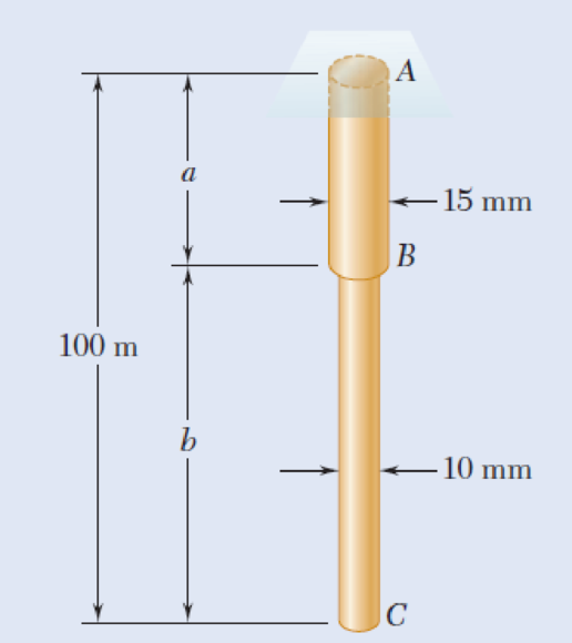
Two brass rods AB and BC, each of uniform diameter, will be brazed together at B to form a nonuniform rod of total length 100 m that will be suspended from a support at A as shown. Knowing that the density of brass is 8470 kg/m3, determine (a) the length of rod AB for which the maximum normal stress in ABC is minimum, (b) the corresponding value of the maximum normal stress.
Fig. P1.6
(a)
The length of brass rod AB such that the maximum normal stress in ABC is minimum.
Answer to Problem 6P
The length of brass rod AB such that the maximum normal stress in ABC is minimum as
Explanation of Solution
Given information:
The total length of the rod is
The length of rod AB is a.
The length of rod BC is
The density of the brass is
The diameter of the rod AB is
The diameter of the rod BC is
Calculation:
Calculate the area
Here,
Substitute
Calculate the area
Here,
Substitute
Calculate the weights
Here,
Substitute
Calculate the weights
Here,
Substitute
Find the force
Here,
Substitute
Find the normal stress acting at point A using the formula:
Here,
Substitute
Find the normal stress acting at point B using the formula:
Here,
Consider
Substitute
Find the length of brass rod AB for the maximum stress in ABC as minimum:
Here,
Substitute
Thus, the length of brass rod AB is
(b)
The value of maximum normal stress of brass rods.
Answer to Problem 6P
The maximum normal stress of brass rods is
Explanation of Solution
Calculation:
Find the maximum normal stress of brass rod using the relation:
Substitute
Substitute
Thus, the maximum normal stress of brass rods is
Want to see more full solutions like this?
Chapter 1 Solutions
EBK MECHANICS OF MATERIALS
Additional Engineering Textbook Solutions
Vector Mechanics For Engineers
BASIC BIOMECHANICS
Mechanics of Materials (10th Edition)
Database Concepts (8th Edition)
Electric Circuits. (11th Edition)
Starting Out With Visual Basic (8th Edition)


- T₁ F Rd = 0.2 m md = 2 kg T₂ Tz1 Rc = 0.4 m mc = 5 kg m = 3 kgarrow_forward2. Find a basis of solutions by the Frobenius method. Try to identify the series as expansions of known functions. (x + 2)²y" + (x + 2)y' - y = 0 ; Hint: Let: z = x+2arrow_forward1. Find a power series solution in powers of x. y" - y' + x²y = 0arrow_forward
- 3. Find a basis of solutions by the Frobenius method. Try to identify the series as expansions of known functions. 8x2y" +10xy' + (x 1)y = 0 -arrow_forwardHello I was going over the solution for this probem and I'm a bit confused on the last part. Can you please explain to me 1^4 was used for the Co of the tubular cross section? Thank you!arrow_forwardBlood (HD = 0.45 in large diameter tubes) is forced through hollow fiber tubes that are 20 µm in diameter.Equating the volumetric flowrate expressions from (1) assuming marginal zone theory and (2) using an apparentviscosity for the blood, estimate the marginal zone thickness at this diameter. The viscosity of plasma is 1.2 cParrow_forward
- Q2: Find the shear load on bolt A for the connection shown in Figure 2. Dimensions are in mm Fig. 2 24 0-0 0-0 A 180kN (10 Markarrow_forwarddetermine the direction and magnitude of angular velocity ω3 of link CD in the four-bar linkage using the relative velocity graphical methodarrow_forwardFour-bar linkage mechanism, AB=40mm, BC=60mm, CD=70mm, AD=80mm, =60°, w1=10rad/s. Determine the direction and magnitude of w3 using relative motion graphical method. A B 2 3 77777 477777arrow_forward
- Four-bar linkage mechanism, AB=40mm, BC=60mm, CD=70mm, AD=80mm, =60°, w1=10rad/s. Determine the direction and magnitude of w3 using relative motion graphical method. A B 2 3 77777 477777arrow_forwardThe evaporator of a vapor compression refrigeration cycle utilizing R-123 as the refrigerant isbeing used to chill water. The evaporator is a shell and tube heat exchanger with the water flowingthrough the tubes. The water enters the heat exchanger at a temperature of 54°F. The approachtemperature difference of the evaporator is 3°R. The evaporating pressure of the refrigeration cycleis 4.8 psia and the condensing pressure is 75 psia. The refrigerant is flowing through the cycle witha flow rate of 18,000 lbm/hr. The R-123 leaves the evaporator as a saturated vapor and leaves thecondenser as a saturated liquid. Determine the following:a. The outlet temperature of the chilled waterb. The volumetric flow rate of the chilled water (gpm)c. The UA product of the evaporator (Btu/h-°F)d. The heat transfer rate between the refrigerant and the water (tons)arrow_forward(Read image) (Answer given)arrow_forward
 Elements Of ElectromagneticsMechanical EngineeringISBN:9780190698614Author:Sadiku, Matthew N. O.Publisher:Oxford University Press
 Mechanics of Materials (10th Edition)Mechanical EngineeringISBN:9780134319650Author:Russell C. HibbelerPublisher:PEARSON
 Thermodynamics: An Engineering ApproachMechanical EngineeringISBN:9781259822674Author:Yunus A. Cengel Dr., Michael A. BolesPublisher:McGraw-Hill Education
 Control Systems EngineeringMechanical EngineeringISBN:9781118170519Author:Norman S. NisePublisher:WILEY
 Mechanics of Materials (MindTap Course List)Mechanical EngineeringISBN:9781337093347Author:Barry J. Goodno, James M. GerePublisher:Cengage Learning
 Engineering Mechanics: StaticsMechanical EngineeringISBN:9781118807330Author:James L. Meriam, L. G. Kraige, J. N. BoltonPublisher:WILEY