
Videos
Atmospheric air enters an air-conditioning system at 30°C and 70 percent relative humidity with a volume flow rate of 4 m3/min and is cooled to 20°C and 20 percent relative humidity at a pressure of 1 atm. The system uses refrigerant-134a as the cooling fluid that enters the cooling section at 350 kPa with a quality of 20 percent and leaves as a saturated vapor. Show the process on the psychrometric chart. What is the heat transfer from the air to the cooling coils, in kW? If any water is condensed from the air, how much water will be condensed from the atmospheric air per min? Determine the mass flow rate of the refrigerant, in kg/min.
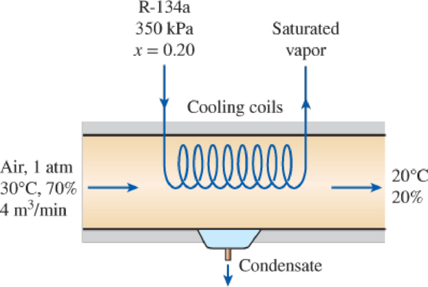
FIGURE P14–132
Show the process on the psychrometric chart; find the heat transfer from the air to the cooling coils, how much water will be condensed from the atmospheric air per min and the mass flow rate of the refrigerant.
Answer to Problem 132RP
The process on the psychrometric chart is shown below in Figure (1), the heat transfer from the air to the cooling coils is
Explanation of Solution
As the process is a steady flow and thus the mass flow rate of dry air remains constant during the entire process.
Here, the mass flow rate of air at inlet is
Express the mass flow rate of dry air.
Here, volume flow rate at inlet is
Express the mass flow rate of vapor at inlet.
Here, specific humidity at state 1 is
Express the mass flow rate of vapor at exit.
Here, specific humidity at state 2 is
Express the rate of condensation of water.
Express the enthalpy of condensate water.
Here, enthalpy of saturation liquid at temperature of
Express the rate required heat transfer rate from the atmospheric air to the evaporator fluid from an energy balance on the control volume.
Here, enthalpy at state 1 and 2 is
Express enthalpy of refrigerant at inlet.
Here, quality of refrigerant at inlet is
Express enthalpy of refrigerant at exit.
Here, quality of refrigerant at exit is
Express the mass flow rate of the refrigerant.
Here, enthalpy of refrigerant at inlet and exit is
Conclusion:
Show the psychrometric diagram as in Figure (1).
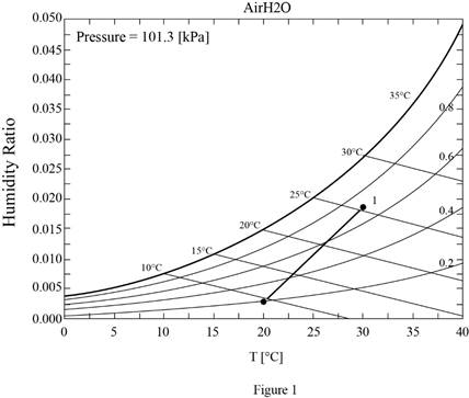
Hence, the psychrometric diagram is shown in Figure (1).
Refer Figure A-31, “psychometric chart at
Refer Figure A-31, “psychometric chart at
Substitute
Substitute
Substitute
Substitute
Hence, the amount of water condensed from the atmospheric air per min is
Refer Table A-4, “saturated water-temperature table”, and write the enthalpy of condensate water at temperature of
Here, enthalpy of saturation liquid is
Substitute
Substitute
Hence, the heat transfer from the air to the cooling coils is
Refer Table A-12, saturated refrigerant-134a-presure table”, and write enthalpy of saturation liquid at pressure of
Write the formula of interpolation method of two variables.
Here, the variables denote by x and y pressure and enthalpy of saturation liquid respectively.
Show the enthalpy of saturation liquid corresponding to pressure as in Table (1).
|
Pressure |
Enthalpy of saturation liquid |
| 320 | 55.14 |
| 350 | |
| 360 | 59.70 |
Substitute
Thus, the enthalpy of saturation liquid at pressure of
Refer Table A-12, saturated refrigerant-134a-presure table”, and write enthalpy of saturation vapor at pressure of
Show the enthalpy of saturation vapor corresponding to pressure as in Table (2).
|
Pressure |
Enthalpy of saturation liquid |
| 320 | 251.93 |
| 350 | |
| 360 | 253.86 |
Use excels and tabulates the values form Table (2) in Equation (X) to get,
Substitute
Substitute
Substitute
Hence, the mass flow rate of the refrigerant is
Want to see more full solutions like this?
Chapter 14 Solutions
THERMODYNAMICS: ENG APPROACH LOOSELEAF


- 6. A part of the structure for a factory automation system is a beam that spans 30.0 in as shown in Figure P5-6. Loads are applied at two points, each 8.0 in from a support. The left load F₁ = 1800 lb remains constantly applied, while the right load F₂ = 1800 lb is applied and removed fre- quently as the machine cycles. Evaluate the beam at both B and C. A 8 in F₁ = 1800 lb 14 in F2 = 1800 lb 8 in D RA B C 4X2X1/4 Steel tube Beam cross section RDarrow_forward30. Repeat Problem 28, except using a shaft that is rotating and transmitting a torque of 150 N⚫m from the left bear- ing to the middle of the shaft. Also, there is a profile key- seat at the middle under the load.arrow_forward28. The shaft shown in Figure P5-28 is supported by bear- ings at each end, which have bores of 20.0 mm. Design the shaft to carry the given load if it is steady and the shaft is stationary. Make the dimension a as large as pos- sible while keeping the stress safe. Determine the required d = 20mm D = ? R = ?| 5.4 kN d=20mm Length not to scale -a = ?- +а= a = ? + -125 mm- -250 mm- FIGURE P5-28 (Problems 28, 29, and 30)arrow_forward
- 12. Compute the estimated actual endurance limit for SAE 4130 WQT 1300 steel bar with a rectangular cross sec- tion of 20.0 mm by 60 mm. It is to be machined and subjected to repeated and reversed bending stress. A reli- ability of 99% is desired.arrow_forward28. The shaft shown in Figure P5-28 is supported by bear- ings at each end, which have bores of 20.0 mm. Design the shaft to carry the given load if it is steady and the shaft is stationary. Make the dimension a as large as pos- sible while keeping the stress safe. Determine the required d = 20mm D = ? R = ?| 5.4 kN d=20mm Length not to scale -a = ?- +а= a = ? + -125 mm- -250 mm- FIGURE P5-28 (Problems 28, 29, and 30)arrow_forward2. A strut in a space frame has a rectangular cross section of 10.0 mm by 30.0 mm. It sees a load that varies from a tensile force of 20.0 kN to a compressive force of 8.0 kN.arrow_forward
- find stress at Qarrow_forwardI had a theoretical question about attitude determination. In the attached images, I gave two axis and angles. The coefficient of the axes are the same and the angles are the same. The only difference is the vector basis. Lets say there is a rotation going from n hat to b hat. Then, you introduce a intermediate rotation s hat. So, I want to know if the DCM produced from both axis and angles will be the same or not. Does the vector basis affect the numerical value of the DCM? The DCM formula only cares about the coefficient of the axis and the angle. So, they should be the same right?arrow_forward3-15. A small fixed tube is shaped in the form of a vertical helix of radius a and helix angle y, that is, the tube always makes an angle y with the horizontal. A particle of mass m slides down the tube under the action of gravity. If there is a coefficient of friction μ between the tube and the particle, what is the steady-state speed of the particle? Let y γ 30° and assume that µ < 1/√3.arrow_forward
- The plate is moving at 0.6 mm/s when the force applied to the plate is 4mN. If the surface area of the plate in contact with the liquid is 0.5 m^2, deterimine the approximate viscosity of the liquid, assuming that the velocity distribution is linear.arrow_forward3-9. Given that the force acting on a particle has the following components: Fx = −x + y, Fy = x − y + y², F₂ = 0. Solve for the potential energy V. -arrow_forward2.5 (B). A steel rod of cross-sectional area 600 mm² and a coaxial copper tube of cross-sectional area 1000 mm² are firmly attached at their ends to form a compound bar. Determine the stress in the steel and in the copper when the temperature of the bar is raised by 80°C and an axial tensile force of 60 kN is applied. For steel, E = 200 GN/m² with x = 11 x 10-6 per °C. E = 100 GN/m² with α = 16.5 × 10⁻⁶ For copper, per °C. [E.I.E.] [94.6, 3.3 MN/m².]arrow_forward
 Elements Of ElectromagneticsMechanical EngineeringISBN:9780190698614Author:Sadiku, Matthew N. O.Publisher:Oxford University Press
 Mechanics of Materials (10th Edition)Mechanical EngineeringISBN:9780134319650Author:Russell C. HibbelerPublisher:PEARSON
 Thermodynamics: An Engineering ApproachMechanical EngineeringISBN:9781259822674Author:Yunus A. Cengel Dr., Michael A. BolesPublisher:McGraw-Hill Education
 Control Systems EngineeringMechanical EngineeringISBN:9781118170519Author:Norman S. NisePublisher:WILEY
 Mechanics of Materials (MindTap Course List)Mechanical EngineeringISBN:9781337093347Author:Barry J. Goodno, James M. GerePublisher:Cengage Learning
 Engineering Mechanics: StaticsMechanical EngineeringISBN:9781118807330Author:James L. Meriam, L. G. Kraige, J. N. BoltonPublisher:WILEY