
Fundamentals of Electric Circuits
6th Edition
ISBN: 9780078028229
Author: Charles K Alexander, Matthew Sadiku
Publisher: McGraw-Hill Education
expand_more
expand_more
format_list_bulleted
Videos
Textbook Question
Chapter 14, Problem 81P
The circuit shown in Fig. 14.98 has the impedance
Find:
- (a) the values of R, L, C, and G
- (b) the element values that will raise the resonant frequency by a factor of 103 by frequency scaling
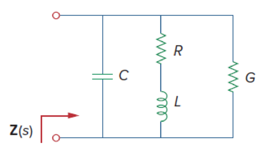
Figure 14.98
Expert Solution & Answer
Want to see the full answer?
Check out a sample textbook solution
Students have asked these similar questions
1. Figure 2 shows a filter. Transpose the filter by first converting it into a DFG
and redraw the transposed filter
+
(✗
D
+
×
y(n)
✗
(☑
(x)
(+
4D
(×→+) D
u(n)
✗
(☑
+
Figure 2: Filter structure.
D
D
Design a 4-bit circuit with 2 outputs A and B. A is 1 if the input is divisible by 2 and B is 1 if the input is divisible by 3. Simplify A and B and implement the circuit.a. Draw KMAP for A and B and simplify them and then draw circuit
Question 1. Design a 4-bit combinational circuit for a 2’s complementer. The circuit generates at the output the 2’s complement of the input binary numbers.a) Complete the following truth table. A, B, C, D indicate the input binary number to be complement- ed using 2’s complement and W, X, Y, Z represent the output 2’s complement of the input binary number. The variable D is the least significant bit and A is the most significant bit of the binary number.b) Simplify the Boolean function W in its Sum-of-Products (SOP) form using a K-Map (you do not have to show the circuit) and provide its simplified Boolean expression.c) Show that the Boolean function W can be realized using exclusive-OR (XOR) gates and OR gates draw its corresponding logic circuit.d) Simplify the Boolean function Z in its Product-of-Sums (POS) form using a K-Map, provide its simplified Boolean expression and draw its corresponding logic circuit.
Chapter 14 Solutions
Fundamentals of Electric Circuits
Ch. 14.2 - Obtain the transfer function VoVs of the RL...Ch. 14.2 - Prob. 2PPCh. 14.4 - Draw the Bode plots for the transfer function...Ch. 14.4 - Sketch the Bode plots for H()=50j(j+4)(j+10)2Ch. 14.4 - Construct the Bode plots for H(s)=10s(s2+80s+400)Ch. 14.4 - Obtain the transfer function H() corresponding to...Ch. 14.5 - A series-connected circuit has R = 4 and L = 25...Ch. 14.6 - A parallel resonant circuit has R = 100 k, L = 50...Ch. 14.6 - Calculate the resonant frequency of the circuit in...Ch. 14.7 - For the circuit in Fig. 14.40, obtain the transfer...
Ch. 14.7 - Design a band-pass filter of the form in Fig....Ch. 14.8 - Design a high-pass filter with a high-frequency...Ch. 14.8 - Design a notch filter based on Fig. 14.47 for 0 =...Ch. 14.9 - Prob. 14PPCh. 14.10 - Obtain the frequency response of the circuit in...Ch. 14.10 - Consider the network in Fig. 14.57. Use PSpice to...Ch. 14.12 - For an FM radio receiver, the incoming wave is in...Ch. 14.12 - Repeat Example 14.18 for band-pass filter BP6....Ch. 14.12 - If each speaker in Fig. 14.66 has an 8- resistance...Ch. 14 - Prob. 1RQCh. 14 - On the Bode magnitude plot, the slope of 1/5+j2...Ch. 14 - On the Bode phase plot for 0.5 50, the slope of...Ch. 14 - How much inductance is needed to resonate at 5 kHz...Ch. 14 - The difference between the half-power frequencies...Ch. 14 - Prob. 6RQCh. 14 - Prob. 7RQCh. 14 - Prob. 8RQCh. 14 - What kind of filter can be used to select a signal...Ch. 14 - A voltage source supplies a signal of constant...Ch. 14 - Find the transfer function Io/Ii of the RL circuit...Ch. 14 - Using Fig. 14.69, design a problem to help other...Ch. 14 - For the circuit shown in Fig. 14.70, find H(s) =...Ch. 14 - Find the transfer function H(s) = Vo/Vi of the...Ch. 14 - For the circuit shown in Fig. 14.72, find H(s) =...Ch. 14 - For the circuit shown in Fig. 14.73, find H(s) =...Ch. 14 - Calculate |H()| if HdB equals (a) 0.1 dB (b) 5 dB...Ch. 14 - Design a problem to help other students calculate...Ch. 14 - A ladder network has a voltage gain of...Ch. 14 - Design a problem to help other students better...Ch. 14 - Sketch the Bode plots for H()=0.2(10+j)j(2+j)Ch. 14 - A transfer function is given by...Ch. 14 - Construct the Bode plots for...Ch. 14 - Draw the Bode plots for H()=250(j+1)j(2+10j+25)Ch. 14 - Prob. 15PCh. 14 - Sketch Bode magnitude and phase plots for...Ch. 14 - Sketch the Bode plots for G(s)=s(s+2)2(s+1), s = jCh. 14 - A linear network has this transfer function...Ch. 14 - Sketch the asymptotic Bode plots of the magnitude...Ch. 14 - Design a more complex problem than given in Prob....Ch. 14 - Sketch the magnitude Bode plot for...Ch. 14 - Find the transfer function H() with the Bode...Ch. 14 - The Bode magnitude plot of H() is shown in Fig....Ch. 14 - The magnitude plot in Fig. 14.76 represents the...Ch. 14 - A series RLC network has R = 2 k, L = 40 mH, and C...Ch. 14 - Design a problem to help other students better...Ch. 14 - Design a series RLC resonant circuit with 0 = 40...Ch. 14 - Design a series RLC circuit with B = 20 rad/s and...Ch. 14 - Let vs = 20 cos(at) V in the circuit of Fig....Ch. 14 - A circuit consisting of a coil with inductance 10...Ch. 14 - Design a parallel resonant RLC circuit with 0 =...Ch. 14 - Design a problem to help other students better...Ch. 14 - A parallel resonant circuit with a bandwidth of 40...Ch. 14 - A parallel RLC circuit has R = 100 k, L = 100 mH,...Ch. 14 - A parallel RLC circuit has R = 10 k, L = 100 mH,...Ch. 14 - It is expected that a parallel RLC resonant...Ch. 14 - Rework Prob. 14.25 if the elements are connected...Ch. 14 - Find the resonant frequency of the circuit in Fig....Ch. 14 - For the tank circuit in Fig. 14.79, find the...Ch. 14 - Prob. 40PCh. 14 - Using Fig. 14.80, design a problem to help other...Ch. 14 - For the circuits in Fig. 14.81, find the resonant...Ch. 14 - Calculate the resonant frequency of each of the...Ch. 14 - For the circuit in Fig. 14.83, find: (a) the...Ch. 14 - For the circuit shown in Fig. 14.84. find 0, B,...Ch. 14 - For the network illustrated in Fig. 14.85, find...Ch. 14 - Prob. 47PCh. 14 - Find the transfer function Vo/Vs of the circuit in...Ch. 14 - Design a problem to help other students better...Ch. 14 - Determine what type of filter is in Fig. 14.87....Ch. 14 - Design an RL low-pass filter that uses a 40-mH...Ch. 14 - Design a problem to help other students better...Ch. 14 - Design a series RLC type band-pass filter with...Ch. 14 - Design a passive band-stop filter with 0 = 10...Ch. 14 - Determine the range of frequencies that will be...Ch. 14 - (a) Show that for a band-pass filter,...Ch. 14 - Determine the center frequency and bandwidth of...Ch. 14 - The circuit parameters for a series RLC band-stop...Ch. 14 - Find the bandwidth and center frequency of the...Ch. 14 - Obtain the transfer function of a high-pass filter...Ch. 14 - Find the transfer function for each of the active...Ch. 14 - The filter in Fig. 14.90(b) has a 3-dB cutoff...Ch. 14 - Design an active first-order high-pass filter with...Ch. 14 - Obtain the transfer function of the active filter...Ch. 14 - A high-pass filter is shown in Fig. 14.92. Show...Ch. 14 - A general first-order filter is shown in Fig....Ch. 14 - Design an active low-pass filter with dc gain of...Ch. 14 - Design a problem to help other students better...Ch. 14 - Design the filter in Fig. 14.94 to meet the...Ch. 14 - A second-order active filter known as a...Ch. 14 - Use magnitude and frequency scaling on the circuit...Ch. 14 - Design a problem to help other students better...Ch. 14 - Calculate the values of R, L, and C that will...Ch. 14 - Prob. 74PCh. 14 - In an RLC circuit, R = 20 , L = 4 H, and C = 1 F....Ch. 14 - Given a parallel RLC circuit with R = 5 k, L = 10...Ch. 14 - A series RLC circuit has R = 10 , 0 = 40 rad/s,...Ch. 14 - Redesign the circuit in Fig. 14.85 so that all...Ch. 14 - Refer to the network in Fig. 14.96. (a) Find...Ch. 14 - (a) For the circuit in Fig. 14.97, draw the new...Ch. 14 - The circuit shown in Fig. 14.98 has the impedance...Ch. 14 - Scale the low-pass active filter in Fig. 14.99 so...Ch. 14 - The op amp circuit in Fig. 14.100 is to be...Ch. 14 - Using PSpice or MultiSim, obtain the frequency...Ch. 14 - Use PSpice or MultiSim to obtain the magnitude and...Ch. 14 - Using Fig. 14.103, design a problem to help other...Ch. 14 - In the interval 0.1 f 100 Hz, plot the response...Ch. 14 - Use PSpice or MultiSim to generate the magnitude...Ch. 14 - Obtain the magnitude plot of the response Vo in...Ch. 14 - Obtain the frequency response of the circuit in...Ch. 14 - For the tank circuit of Fig. 14.79, obtain the...Ch. 14 - Using PSpice or MultiSim, plot the magnitude of...Ch. 14 - For the phase shifter circuit shown in Fig....Ch. 14 - For an emergency situation, an engineer needs to...Ch. 14 - A series-tuned antenna circuit consists of a...Ch. 14 - The crossover circuit in Fig. 14.108 is a low-pass...Ch. 14 - The crossover circuit in Fig. 14.109 is a...Ch. 14 - A certain electronic test circuit produced a...Ch. 14 - In an electronic device, a series circuit is...Ch. 14 - In a certain application, a simple RC low-pass...Ch. 14 - In an amplifier circuit, a simple RC high-pass...Ch. 14 - Practical RC filter design should allow for source...Ch. 14 - The RC circuit in Fig. 14.111 is used for a lead...Ch. 14 - A low-quality-factor, double-tuned band-pass...
Knowledge Booster


Learn more about
Need a deep-dive on the concept behind this application? Look no further. Learn more about this topic, electrical-engineering and related others by exploring similar questions and additional content below.Similar questions
- Given the function F(x,y,z)= y +x′za. Expand F to its Product-of-Maxterms formb. Implement F with NAND gates only.arrow_forward+ Consider the following circuit. 25 nF 4 ΚΩ ww HE + 2 H Vo 10 ΚΩ a) [5 pts] The frequency of the source voltage in the circuit is adjusted until ig is in phase with vg. What is the value of oo in radians per second? Show calculations in the report. b) [5 pts] If vg = 45 cosoot V (where o is the frequency found in [a]), what is the steady-state expression for Vo? Show calculations in the report. c) [10 pts] Simulate the circuit in Multisim using the frequency found in [a] and verify the total impedance, Ig and Vo. Add the expressions to find the Total impedance and Io as explained in question 1. When finding Vo use the Differential Voltage probe and place the + and - probes as shown below (note that only that part of the circuit is shown below.) Double click on the + probe to open the properties window. Change the RefDes to Vo and select Show RefDes. This will display the name of the probe as Vo on the schematic. Include the schematic and the Grapher view window in your report. Vo +-…arrow_forwardConsider the following circuit with v(t) = 250 sin(2500t) V. 62.5 Ω w 300 Ω i₁ + Vs 50 mH 500 Ω 1 μF (a) [14 pts] Obtain the following and include the calculations in the report. Vm, o, Frequency (f), ZL, ZC, Total Impedance (Ztot), Io, Steady-state expression for io:arrow_forward
- Not use ai pleasearrow_forwardAdd the two AC voltages given below by converting them to their phasor forms. Express your final answer as a sinusoid in the time domain with phase angles measured in radians. You must show your all your work for the complex matharrow_forwardDetermine a) ic1(t=0-) and vc1(t=0-), i.e. just before the switch changes positions (just before t = 0 s) b) ic1(t=0) and vc1(t=0), i.e. just after the switch changes positions c) ic1(t=∞) and vc1(t=∞), i.e. at steady state after the switch changes positions d) The expression for vc1(t) for t ≥ 0 sarrow_forward
- After having been in position 1 for a long time, the switch in the circuit below was moved to position 2 at t = 0 s. Determine: a) iL(t=0-) and vL(t=0-), i.e., just before the switch changes positions (just before t = 0 s) b) iL(t=0) and vL(t=0), i.e., just after the switch changes positions c) iL(t=∞) and vL(t=∞), i.e., at steady state after the switch changes positions d) The expression for iL(t) for t ≥ 0 sarrow_forwardCan you please answer these three questions.arrow_forwardThe counter-emf of a motor is always slightly less than the applied armature volt- age. Explain. Name two methods that are used to vary the speed of a de motor. Explain why the armature current of a shunt motor decreases as the motor accelerates.arrow_forward
- The compound motor has 1200 turns on the shunt winding and 25 turns on the series winding, per pole. The shunt field has a total resistance of 115 ohms, and the nominal armature current is 23 A. If the motor is connected to a 230 V line, calculate the following: a. The mmf per pole at full-load. b. The mmf at no-load.arrow_forwardCan be solve this problem without ai chatgpt .arrow_forwardNot use ai pleasearrow_forward
arrow_back_ios
SEE MORE QUESTIONS
arrow_forward_ios
Recommended textbooks for you
 Introductory Circuit Analysis (13th Edition)Electrical EngineeringISBN:9780133923605Author:Robert L. BoylestadPublisher:PEARSON
 Delmar's Standard Textbook Of ElectricityElectrical EngineeringISBN:9781337900348Author:Stephen L. HermanPublisher:Cengage Learning
 Programmable Logic ControllersElectrical EngineeringISBN:9780073373843Author:Frank D. PetruzellaPublisher:McGraw-Hill Education
 Fundamentals of Electric CircuitsElectrical EngineeringISBN:9780078028229Author:Charles K Alexander, Matthew SadikuPublisher:McGraw-Hill Education
 Electric Circuits. (11th Edition)Electrical EngineeringISBN:9780134746968Author:James W. Nilsson, Susan RiedelPublisher:PEARSON
 Engineering ElectromagneticsElectrical EngineeringISBN:9780078028151Author:Hayt, William H. (william Hart), Jr, BUCK, John A.Publisher:Mcgraw-hill Education,
Introductory Circuit Analysis (13th Edition)
Electrical Engineering
ISBN:9780133923605
Author:Robert L. Boylestad
Publisher:PEARSON
Delmar's Standard Textbook Of Electricity
Electrical Engineering
ISBN:9781337900348
Author:Stephen L. Herman
Publisher:Cengage Learning
Programmable Logic Controllers
Electrical Engineering
ISBN:9780073373843
Author:Frank D. Petruzella
Publisher:McGraw-Hill Education
Fundamentals of Electric Circuits
Electrical Engineering
ISBN:9780078028229
Author:Charles K Alexander, Matthew Sadiku
Publisher:McGraw-Hill Education
Electric Circuits. (11th Edition)
Electrical Engineering
ISBN:9780134746968
Author:James W. Nilsson, Susan Riedel
Publisher:PEARSON
Engineering Electromagnetics
Electrical Engineering
ISBN:9780078028151
Author:Hayt, William H. (william Hart), Jr, BUCK, John A.
Publisher:Mcgraw-hill Education,
02 - Sinusoidal AC Voltage Sources in Circuits, Part 1; Author: Math and Science;https://www.youtube.com/watch?v=8zMiIHVMfaw;License: Standard Youtube License