
Fundamentals of Electric Circuits
6th Edition
ISBN: 9780078028229
Author: Charles K Alexander, Matthew Sadiku
Publisher: McGraw-Hill Education
expand_more
expand_more
format_list_bulleted
Videos
Textbook Question
Chapter 14, Problem 24P
The magnitude plot in Fig. 14.76 represents the transfer function of a preamplifier. Find H(s).
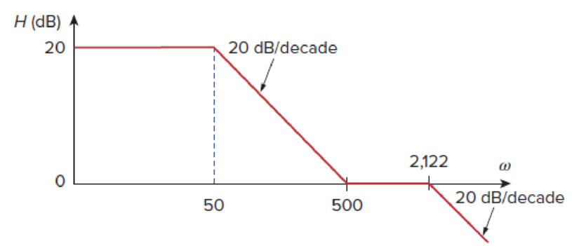
Figure 14.76
Expert Solution & Answer
Want to see the full answer?
Check out a sample textbook solution
Students have asked these similar questions
For the transistor amplifier shown, R₁-11kQ, R2=6kQ, Rc=2kQ, RE-3kQ and R₁=2k0.
(i) Draw d.c. load line
(ii) Determine the DC operating point
(iii) Draw a.c. load line. Assume V_BE = 0.7 V. and determine the new operating point
+ Vcc = 15 V
RC
Cc
Cin
R1
wwwwww
wwwww
R₁₂
RE
CE
RL
the first part is
the second part
write your answer such as: (AND, OR, INVERTER, NAND, NOR)
D₁
AK
D,
R₁
B
K
First Part?
the third part is
, and the total are
R4
R7
Output
R5
R₁
T
R6
R3
-UBB
Second Part?
Third Part?
Total?
A multistage amplifier has six stages each of which has a power gain of 40. what is the
- Total gain of the amplifier in db
?
ii- If the negative feedback of 15db is employed, find the resultant gain
Chapter 14 Solutions
Fundamentals of Electric Circuits
Ch. 14.2 - Obtain the transfer function VoVs of the RL...Ch. 14.2 - Prob. 2PPCh. 14.4 - Draw the Bode plots for the transfer function...Ch. 14.4 - Sketch the Bode plots for H()=50j(j+4)(j+10)2Ch. 14.4 - Construct the Bode plots for H(s)=10s(s2+80s+400)Ch. 14.4 - Obtain the transfer function H() corresponding to...Ch. 14.5 - A series-connected circuit has R = 4 and L = 25...Ch. 14.6 - A parallel resonant circuit has R = 100 k, L = 50...Ch. 14.6 - Calculate the resonant frequency of the circuit in...Ch. 14.7 - For the circuit in Fig. 14.40, obtain the transfer...
Ch. 14.7 - Design a band-pass filter of the form in Fig....Ch. 14.8 - Design a high-pass filter with a high-frequency...Ch. 14.8 - Design a notch filter based on Fig. 14.47 for 0 =...Ch. 14.9 - Prob. 14PPCh. 14.10 - Obtain the frequency response of the circuit in...Ch. 14.10 - Consider the network in Fig. 14.57. Use PSpice to...Ch. 14.12 - For an FM radio receiver, the incoming wave is in...Ch. 14.12 - Repeat Example 14.18 for band-pass filter BP6....Ch. 14.12 - If each speaker in Fig. 14.66 has an 8- resistance...Ch. 14 - Prob. 1RQCh. 14 - On the Bode magnitude plot, the slope of 1/5+j2...Ch. 14 - On the Bode phase plot for 0.5 50, the slope of...Ch. 14 - How much inductance is needed to resonate at 5 kHz...Ch. 14 - The difference between the half-power frequencies...Ch. 14 - Prob. 6RQCh. 14 - Prob. 7RQCh. 14 - Prob. 8RQCh. 14 - What kind of filter can be used to select a signal...Ch. 14 - A voltage source supplies a signal of constant...Ch. 14 - Find the transfer function Io/Ii of the RL circuit...Ch. 14 - Using Fig. 14.69, design a problem to help other...Ch. 14 - For the circuit shown in Fig. 14.70, find H(s) =...Ch. 14 - Find the transfer function H(s) = Vo/Vi of the...Ch. 14 - For the circuit shown in Fig. 14.72, find H(s) =...Ch. 14 - For the circuit shown in Fig. 14.73, find H(s) =...Ch. 14 - Calculate |H()| if HdB equals (a) 0.1 dB (b) 5 dB...Ch. 14 - Design a problem to help other students calculate...Ch. 14 - A ladder network has a voltage gain of...Ch. 14 - Design a problem to help other students better...Ch. 14 - Sketch the Bode plots for H()=0.2(10+j)j(2+j)Ch. 14 - A transfer function is given by...Ch. 14 - Construct the Bode plots for...Ch. 14 - Draw the Bode plots for H()=250(j+1)j(2+10j+25)Ch. 14 - Prob. 15PCh. 14 - Sketch Bode magnitude and phase plots for...Ch. 14 - Sketch the Bode plots for G(s)=s(s+2)2(s+1), s = jCh. 14 - A linear network has this transfer function...Ch. 14 - Sketch the asymptotic Bode plots of the magnitude...Ch. 14 - Design a more complex problem than given in Prob....Ch. 14 - Sketch the magnitude Bode plot for...Ch. 14 - Find the transfer function H() with the Bode...Ch. 14 - The Bode magnitude plot of H() is shown in Fig....Ch. 14 - The magnitude plot in Fig. 14.76 represents the...Ch. 14 - A series RLC network has R = 2 k, L = 40 mH, and C...Ch. 14 - Design a problem to help other students better...Ch. 14 - Design a series RLC resonant circuit with 0 = 40...Ch. 14 - Design a series RLC circuit with B = 20 rad/s and...Ch. 14 - Let vs = 20 cos(at) V in the circuit of Fig....Ch. 14 - A circuit consisting of a coil with inductance 10...Ch. 14 - Design a parallel resonant RLC circuit with 0 =...Ch. 14 - Design a problem to help other students better...Ch. 14 - A parallel resonant circuit with a bandwidth of 40...Ch. 14 - A parallel RLC circuit has R = 100 k, L = 100 mH,...Ch. 14 - A parallel RLC circuit has R = 10 k, L = 100 mH,...Ch. 14 - It is expected that a parallel RLC resonant...Ch. 14 - Rework Prob. 14.25 if the elements are connected...Ch. 14 - Find the resonant frequency of the circuit in Fig....Ch. 14 - For the tank circuit in Fig. 14.79, find the...Ch. 14 - Prob. 40PCh. 14 - Using Fig. 14.80, design a problem to help other...Ch. 14 - For the circuits in Fig. 14.81, find the resonant...Ch. 14 - Calculate the resonant frequency of each of the...Ch. 14 - For the circuit in Fig. 14.83, find: (a) the...Ch. 14 - For the circuit shown in Fig. 14.84. find 0, B,...Ch. 14 - For the network illustrated in Fig. 14.85, find...Ch. 14 - Prob. 47PCh. 14 - Find the transfer function Vo/Vs of the circuit in...Ch. 14 - Design a problem to help other students better...Ch. 14 - Determine what type of filter is in Fig. 14.87....Ch. 14 - Design an RL low-pass filter that uses a 40-mH...Ch. 14 - Design a problem to help other students better...Ch. 14 - Design a series RLC type band-pass filter with...Ch. 14 - Design a passive band-stop filter with 0 = 10...Ch. 14 - Determine the range of frequencies that will be...Ch. 14 - (a) Show that for a band-pass filter,...Ch. 14 - Determine the center frequency and bandwidth of...Ch. 14 - The circuit parameters for a series RLC band-stop...Ch. 14 - Find the bandwidth and center frequency of the...Ch. 14 - Obtain the transfer function of a high-pass filter...Ch. 14 - Find the transfer function for each of the active...Ch. 14 - The filter in Fig. 14.90(b) has a 3-dB cutoff...Ch. 14 - Design an active first-order high-pass filter with...Ch. 14 - Obtain the transfer function of the active filter...Ch. 14 - A high-pass filter is shown in Fig. 14.92. Show...Ch. 14 - A general first-order filter is shown in Fig....Ch. 14 - Design an active low-pass filter with dc gain of...Ch. 14 - Design a problem to help other students better...Ch. 14 - Design the filter in Fig. 14.94 to meet the...Ch. 14 - A second-order active filter known as a...Ch. 14 - Use magnitude and frequency scaling on the circuit...Ch. 14 - Design a problem to help other students better...Ch. 14 - Calculate the values of R, L, and C that will...Ch. 14 - Prob. 74PCh. 14 - In an RLC circuit, R = 20 , L = 4 H, and C = 1 F....Ch. 14 - Given a parallel RLC circuit with R = 5 k, L = 10...Ch. 14 - A series RLC circuit has R = 10 , 0 = 40 rad/s,...Ch. 14 - Redesign the circuit in Fig. 14.85 so that all...Ch. 14 - Refer to the network in Fig. 14.96. (a) Find...Ch. 14 - (a) For the circuit in Fig. 14.97, draw the new...Ch. 14 - The circuit shown in Fig. 14.98 has the impedance...Ch. 14 - Scale the low-pass active filter in Fig. 14.99 so...Ch. 14 - The op amp circuit in Fig. 14.100 is to be...Ch. 14 - Using PSpice or MultiSim, obtain the frequency...Ch. 14 - Use PSpice or MultiSim to obtain the magnitude and...Ch. 14 - Using Fig. 14.103, design a problem to help other...Ch. 14 - In the interval 0.1 f 100 Hz, plot the response...Ch. 14 - Use PSpice or MultiSim to generate the magnitude...Ch. 14 - Obtain the magnitude plot of the response Vo in...Ch. 14 - Obtain the frequency response of the circuit in...Ch. 14 - For the tank circuit of Fig. 14.79, obtain the...Ch. 14 - Using PSpice or MultiSim, plot the magnitude of...Ch. 14 - For the phase shifter circuit shown in Fig....Ch. 14 - For an emergency situation, an engineer needs to...Ch. 14 - A series-tuned antenna circuit consists of a...Ch. 14 - The crossover circuit in Fig. 14.108 is a low-pass...Ch. 14 - The crossover circuit in Fig. 14.109 is a...Ch. 14 - A certain electronic test circuit produced a...Ch. 14 - In an electronic device, a series circuit is...Ch. 14 - In a certain application, a simple RC low-pass...Ch. 14 - In an amplifier circuit, a simple RC high-pass...Ch. 14 - Practical RC filter design should allow for source...Ch. 14 - The RC circuit in Fig. 14.111 is used for a lead...Ch. 14 - A low-quality-factor, double-tuned band-pass...
Knowledge Booster


Learn more about
Need a deep-dive on the concept behind this application? Look no further. Learn more about this topic, electrical-engineering and related others by exploring similar questions and additional content below.Similar questions
- 9.36 Consider the finite-state machine logic implementation in Figure P9.36. (a) Determine the next-state and output logic expressions. (b) Determine the number of possible states. J1 Clk K₁ 101 Ут J2 Clk K₂ Clk Figure P9.36 0 y2 10arrow_forward9.34 Consider the finite-state machine logic implementation in Figure P9.34. (a) Determine the next-state and output logic expressions. (b) Determine the number of possible states. (c) Construct a state assigned table. (d) Construct a state table. (e) Construct a state diagram. (f) Determine the function of the finite-state machine. T₁ x Clk Figure P9.34 Q Clk Q الا T₂ Q 32 Clk Q T3 Q Clk Q Узarrow_forward9.35 Consider the finite-state machine logic implementation in Figure P9.35. (a) Determine the next-state and output logic expressions. (b) Determine the number of possible states. (c) Construct a state assigned table. (d) Construct a state table. (e) Construct a state diagram. (f) Determine the function of the finite-state machine. Clk J Clk K₁ 10 Ут J2 Clk K₂ 10 32 Figure P9.35arrow_forward
- 9.56 Using JK flip-flops, design a synchronous counter that counts in the sequence 1, 3, 0, 2, 1, ... The counter counts only when its enable input x is equal to 1; otherwise, the counter is idle.arrow_forward9.65 Using T flip-flops, design a synchronous counter that counts in the sequence 0, 2, 4, 6, 0, ... The counter counts only when its enable input x is equal to 1; otherwise, the counter is idle.arrow_forward2 Using D flip-flops, design a synchronous counter that counts in the sequence 1, 4, 7, 1, The counter counts only when its enable input x is equal to 1; otherwise, the counter is idle.arrow_forward
- Q1: Write a VHDL code to implement the finite state machine described in the state diagram shown below. Clk D 0 CIK Q D 0 Cik Q =arrow_forwardQ1: Consider the finite state machine logic implementation in Fig. shown below: Construct the state diagram. Repeat the circuit design using j-k flip flop. r" Clk Y D' Y, Clk Q D Clk 10 0 22 3'2arrow_forwardQ: Write a VHDL code to implement the finite state machine described in the state diagram shown below. T 2 Clk Q Clk T₂ 0 la Clk T3 Q Cik 0arrow_forward
- Do you happen to know what is the complete circuit?arrow_forwardb) Draw the magnitude and phase bode plot c) Given Cdb=0.02pF, how will the frequency response change, draw the resulting magnitude and phase bode plotplz help me to solve part b and c.arrow_forwardMedium 1 is a lossless dielectric (ε₁, μ₁ = μo, σ₁ = 0) Medium 2 is a perfect electric conductor (PEC) ( 2 = 0, μ2 = μo, σ₂ = ∞) [ Moσ = 0] [ε0 μ₁ σ₂ = ∞ ] (J=σE is finite, E = 0) E(z) Exe² +Пe₁²] 1. For the case εr] = λι = = E2(z)-0 - 1 (vacuum), E₁x 1 V/m and a frequency f = 500 MHz determine: n₁ = 12= 2. Determine: r = T= 3. Using this I show that the total electric field E₁0(z) in region 1 can be written as: E(z) = -2jE, sin(2лz/λ)✰ 4. The magnitude E10(z) will show an interference pattern. The SWR (standing wave ratio) is the Emax/Emin ratio of the magnitude of the total electric field in region 1. What is the SWR? E (z) = 2|E|sin(2лz/2₁)| E" (z) SWR A Imax E(z) Imin 1+r 1-|| tot 5. Roughly SKETCH the magnitude of E10(z) and E20(z) on the graph below. E₁tot(z) tot E20(z) -0.40 -0.30 -0.ło z=0 +0.1b +0.20arrow_forward
arrow_back_ios
SEE MORE QUESTIONS
arrow_forward_ios
Recommended textbooks for you
 Delmar's Standard Textbook Of ElectricityElectrical EngineeringISBN:9781337900348Author:Stephen L. HermanPublisher:Cengage Learning
Delmar's Standard Textbook Of Electricity
Electrical Engineering
ISBN:9781337900348
Author:Stephen L. Herman
Publisher:Cengage Learning
Resonance Circuits: LC Inductor-Capacitor Resonating Circuits; Author: Physics Videos by Eugene Khutoryansky;https://www.youtube.com/watch?v=Mq-PF1vo9QA;License: Standard YouTube License, CC-BY