
Fundamentals of Electric Circuits
6th Edition
ISBN: 9780078028229
Author: Charles K Alexander, Matthew Sadiku
Publisher: McGraw-Hill Education
expand_more
expand_more
format_list_bulleted
Videos
Textbook Question
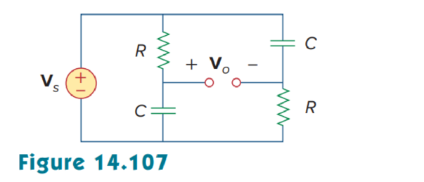
Chapter 14, Problem 93P
For the phase shifter circuit shown in Fig. 14.107, find H = Vo/VS.
Expert Solution & Answer
Want to see the full answer?
Check out a sample textbook solution
Students have asked these similar questions
Choose the appropriate answer
1) Maximum dimension of antenna is 0.5m and operating frequency is 9 GHz, thus the radius of
reactive near field region is
0.562m
1.265m
2.526m
3.265m
2) If distance between transmitter and receiver is 2km and the signal carrier frequency is
300kHz
Rapidly time-varying fields DC field Quasi-static field None
3) The polarization mismatch factor for horizontal polarization wave incident on +z axis is
is if the antenna polarization is circular
0.5
зав
0.707
1
4) Ez 0 and Hz #0 (HE modes): This is the case when neither E nor H field is transverse to the
direction of wave propagation. They are sometimes referred to as
TEM
hybrid modes
TM
TE
5) The normalized radiation intensity of an antenna is represented by:
U(6)=cos²(0) cos2 (30), w/s Half-power beamwidth HPBW is......
28.75
10
0
14.3
Choose the best answer of the following:
1- quasi-static electromagnetic field is the
a) low frequency b)high frequency c) time independent d) none of the above
2- Displacement current is taken to be negligible (compared to the conduction current) if
a) σ>>wε b)σ << wɛ c) σ =0 d) (a and c)
3- The transmission line act as inductor when it terminated by:
a) Open circuit load b) short circuit load c)matched load d)none of the above
4- The scattering aperture equals to the effective aperture when the antenna is:
a) Complex conjugate matching b) short circuit c) open circuit d) none of the above
5- The isotropic point source has directivity of:
a) Infinity b)1 c) 0 d)1.5
I selected a DC-DC converter capable of delivering 120 VDC from a 600 VDC input. When I reached out to the manufacturer, they asked for the total power consumption the converter would need to handle.To estimate this, I calculated the power requirements for the components that will use the 120 VDC supply: interior lighting, end lights, and buzzers. The breakdown is as follows:- Light Bulbs: 16 bulbs at 10 W each = 160 W- Buzzers: 2 buzzers at 5 W each = 10 W- End Lights: 2 lights at 15 W each = 30 W
This results in a total estimated power demand of 200 W.My concern is whether I should request a higher wattage rating for the converter to provide sufficient tolerance and ensure the system operates efficiently without risking an overload.
Note: The DC power system is designed specifically for a trolley
Chapter 14 Solutions
Fundamentals of Electric Circuits
Ch. 14.2 - Obtain the transfer function VoVs of the RL...Ch. 14.2 - Prob. 2PPCh. 14.4 - Draw the Bode plots for the transfer function...Ch. 14.4 - Sketch the Bode plots for H()=50j(j+4)(j+10)2Ch. 14.4 - Construct the Bode plots for H(s)=10s(s2+80s+400)Ch. 14.4 - Obtain the transfer function H() corresponding to...Ch. 14.5 - A series-connected circuit has R = 4 and L = 25...Ch. 14.6 - A parallel resonant circuit has R = 100 k, L = 50...Ch. 14.6 - Calculate the resonant frequency of the circuit in...Ch. 14.7 - For the circuit in Fig. 14.40, obtain the transfer...
Ch. 14.7 - Design a band-pass filter of the form in Fig....Ch. 14.8 - Design a high-pass filter with a high-frequency...Ch. 14.8 - Design a notch filter based on Fig. 14.47 for 0 =...Ch. 14.9 - Prob. 14PPCh. 14.10 - Obtain the frequency response of the circuit in...Ch. 14.10 - Consider the network in Fig. 14.57. Use PSpice to...Ch. 14.12 - For an FM radio receiver, the incoming wave is in...Ch. 14.12 - Repeat Example 14.18 for band-pass filter BP6....Ch. 14.12 - If each speaker in Fig. 14.66 has an 8- resistance...Ch. 14 - Prob. 1RQCh. 14 - On the Bode magnitude plot, the slope of 1/5+j2...Ch. 14 - On the Bode phase plot for 0.5 50, the slope of...Ch. 14 - How much inductance is needed to resonate at 5 kHz...Ch. 14 - The difference between the half-power frequencies...Ch. 14 - Prob. 6RQCh. 14 - Prob. 7RQCh. 14 - Prob. 8RQCh. 14 - What kind of filter can be used to select a signal...Ch. 14 - A voltage source supplies a signal of constant...Ch. 14 - Find the transfer function Io/Ii of the RL circuit...Ch. 14 - Using Fig. 14.69, design a problem to help other...Ch. 14 - For the circuit shown in Fig. 14.70, find H(s) =...Ch. 14 - Find the transfer function H(s) = Vo/Vi of the...Ch. 14 - For the circuit shown in Fig. 14.72, find H(s) =...Ch. 14 - For the circuit shown in Fig. 14.73, find H(s) =...Ch. 14 - Calculate |H()| if HdB equals (a) 0.1 dB (b) 5 dB...Ch. 14 - Design a problem to help other students calculate...Ch. 14 - A ladder network has a voltage gain of...Ch. 14 - Design a problem to help other students better...Ch. 14 - Sketch the Bode plots for H()=0.2(10+j)j(2+j)Ch. 14 - A transfer function is given by...Ch. 14 - Construct the Bode plots for...Ch. 14 - Draw the Bode plots for H()=250(j+1)j(2+10j+25)Ch. 14 - Prob. 15PCh. 14 - Sketch Bode magnitude and phase plots for...Ch. 14 - Sketch the Bode plots for G(s)=s(s+2)2(s+1), s = jCh. 14 - A linear network has this transfer function...Ch. 14 - Sketch the asymptotic Bode plots of the magnitude...Ch. 14 - Design a more complex problem than given in Prob....Ch. 14 - Sketch the magnitude Bode plot for...Ch. 14 - Find the transfer function H() with the Bode...Ch. 14 - The Bode magnitude plot of H() is shown in Fig....Ch. 14 - The magnitude plot in Fig. 14.76 represents the...Ch. 14 - A series RLC network has R = 2 k, L = 40 mH, and C...Ch. 14 - Design a problem to help other students better...Ch. 14 - Design a series RLC resonant circuit with 0 = 40...Ch. 14 - Design a series RLC circuit with B = 20 rad/s and...Ch. 14 - Let vs = 20 cos(at) V in the circuit of Fig....Ch. 14 - A circuit consisting of a coil with inductance 10...Ch. 14 - Design a parallel resonant RLC circuit with 0 =...Ch. 14 - Design a problem to help other students better...Ch. 14 - A parallel resonant circuit with a bandwidth of 40...Ch. 14 - A parallel RLC circuit has R = 100 k, L = 100 mH,...Ch. 14 - A parallel RLC circuit has R = 10 k, L = 100 mH,...Ch. 14 - It is expected that a parallel RLC resonant...Ch. 14 - Rework Prob. 14.25 if the elements are connected...Ch. 14 - Find the resonant frequency of the circuit in Fig....Ch. 14 - For the tank circuit in Fig. 14.79, find the...Ch. 14 - Prob. 40PCh. 14 - Using Fig. 14.80, design a problem to help other...Ch. 14 - For the circuits in Fig. 14.81, find the resonant...Ch. 14 - Calculate the resonant frequency of each of the...Ch. 14 - For the circuit in Fig. 14.83, find: (a) the...Ch. 14 - For the circuit shown in Fig. 14.84. find 0, B,...Ch. 14 - For the network illustrated in Fig. 14.85, find...Ch. 14 - Prob. 47PCh. 14 - Find the transfer function Vo/Vs of the circuit in...Ch. 14 - Design a problem to help other students better...Ch. 14 - Determine what type of filter is in Fig. 14.87....Ch. 14 - Design an RL low-pass filter that uses a 40-mH...Ch. 14 - Design a problem to help other students better...Ch. 14 - Design a series RLC type band-pass filter with...Ch. 14 - Design a passive band-stop filter with 0 = 10...Ch. 14 - Determine the range of frequencies that will be...Ch. 14 - (a) Show that for a band-pass filter,...Ch. 14 - Determine the center frequency and bandwidth of...Ch. 14 - The circuit parameters for a series RLC band-stop...Ch. 14 - Find the bandwidth and center frequency of the...Ch. 14 - Obtain the transfer function of a high-pass filter...Ch. 14 - Find the transfer function for each of the active...Ch. 14 - The filter in Fig. 14.90(b) has a 3-dB cutoff...Ch. 14 - Design an active first-order high-pass filter with...Ch. 14 - Obtain the transfer function of the active filter...Ch. 14 - A high-pass filter is shown in Fig. 14.92. Show...Ch. 14 - A general first-order filter is shown in Fig....Ch. 14 - Design an active low-pass filter with dc gain of...Ch. 14 - Design a problem to help other students better...Ch. 14 - Design the filter in Fig. 14.94 to meet the...Ch. 14 - A second-order active filter known as a...Ch. 14 - Use magnitude and frequency scaling on the circuit...Ch. 14 - Design a problem to help other students better...Ch. 14 - Calculate the values of R, L, and C that will...Ch. 14 - Prob. 74PCh. 14 - In an RLC circuit, R = 20 , L = 4 H, and C = 1 F....Ch. 14 - Given a parallel RLC circuit with R = 5 k, L = 10...Ch. 14 - A series RLC circuit has R = 10 , 0 = 40 rad/s,...Ch. 14 - Redesign the circuit in Fig. 14.85 so that all...Ch. 14 - Refer to the network in Fig. 14.96. (a) Find...Ch. 14 - (a) For the circuit in Fig. 14.97, draw the new...Ch. 14 - The circuit shown in Fig. 14.98 has the impedance...Ch. 14 - Scale the low-pass active filter in Fig. 14.99 so...Ch. 14 - The op amp circuit in Fig. 14.100 is to be...Ch. 14 - Using PSpice or MultiSim, obtain the frequency...Ch. 14 - Use PSpice or MultiSim to obtain the magnitude and...Ch. 14 - Using Fig. 14.103, design a problem to help other...Ch. 14 - In the interval 0.1 f 100 Hz, plot the response...Ch. 14 - Use PSpice or MultiSim to generate the magnitude...Ch. 14 - Obtain the magnitude plot of the response Vo in...Ch. 14 - Obtain the frequency response of the circuit in...Ch. 14 - For the tank circuit of Fig. 14.79, obtain the...Ch. 14 - Using PSpice or MultiSim, plot the magnitude of...Ch. 14 - For the phase shifter circuit shown in Fig....Ch. 14 - For an emergency situation, an engineer needs to...Ch. 14 - A series-tuned antenna circuit consists of a...Ch. 14 - The crossover circuit in Fig. 14.108 is a low-pass...Ch. 14 - The crossover circuit in Fig. 14.109 is a...Ch. 14 - A certain electronic test circuit produced a...Ch. 14 - In an electronic device, a series circuit is...Ch. 14 - In a certain application, a simple RC low-pass...Ch. 14 - In an amplifier circuit, a simple RC high-pass...Ch. 14 - Practical RC filter design should allow for source...Ch. 14 - The RC circuit in Fig. 14.111 is used for a lead...Ch. 14 - A low-quality-factor, double-tuned band-pass...
Knowledge Booster


Learn more about
Need a deep-dive on the concept behind this application? Look no further. Learn more about this topic, electrical-engineering and related others by exploring similar questions and additional content below.Similar questions
- Choose the best answer 1. The minimum value of the directivity of an antenna is.......... a) Unity b) Zero 2. Very low signal strength in antenna. a) Minor lobes b) Null c) Infinite d) None c) Antenna patterns d) Major lobes 3. the maximum directivity of an antenna that normalized far field pattern is given by? 0≤0≤ and 0 ≤≤π/2,3л/2≤ p ≤ 2π E(0, 4) = {(sin 0 ((sin cos² ) 1/2 0 is a) 7.07dB b) 7.7dB elsewhere c) 8.7dB d) 9dB 4. the depth of penetration of 1 MHz wave in sea water which has conductivity mhos/meter and permeability approximately equal to that of free space is a) 25mm b) 25cm c)25m 5. The free space media can be considered as _ a) Lossy media b) lossless media c) good conductor 6. The input impedance is equal to the load impedance when a) l = 2 b)1=22 c)=4 d) 25km d) a and c .... d) a and barrow_forwardQ.1. choose the appropriate answer 1- When neither E nor H field is transverse to the direction of wave propagation. They are sometimes referred to as ...... a) hybrid mode b) TM mode c) TME modes d) TEM mode 2- If PLF-0 dB means......... a) Power is lost 100% b) Power is lost 0% c) Power is lost 50% d) none of the above 3. The half wave dipole is widely used in more applications compared to other linear antenna lengths, that is because..... a) It has high gain b) its easy matching to coaxial 75 Ohm cable c) low loss d) it has small size 4- The mode distribution for the end view waveguide shown below is a) TM12 b) TM21 c) TE20 end view d) TE02 5. When circular right hand polarized wave incident upon a horizontally polarized wave the PLF is a) 0 b)1 c)0.5 d)0.707arrow_forwarda- Single phase transmission line as in the figure below with the radius of the conductor is 0.5 cm, find the inductance of the total system. 4m 4m ao A B ob od 3m 6marrow_forward
- Please don't use ai to answer I will report you answerarrow_forwardA 3-phase, 4-wire distributor supplies a balanced voltage of 400/230 V to a load consisting of 8 A at p.f. 0-7 lagging for R-phase, 10 A at p.f. 0-8 leading for Y phase and 12 A at unity p.f. for B phase. The resistance of each line conductor is 0.4 2. The reactance of neutral is 0.2 2. Calculate the neutral current, the supply voltage for R phase and draw the phasor diagram. The phase sequence is RYB. IN ER VR Refarrow_forwardA 3-phase, 4-wire distributor supplies a balanced voltage of 400/230 V to a load consisting of 50 A at p.f. 0-866 lagging for R-phase, 30 A at p.f. 0-866 leading for Y phase and 30 A at unity pf. for B phase. The resistance of each line conductor is 0-2 Q. The area of X-section of neutral is half of any line conductor: Calculate the supply end voltage for R phase. The phase sequence is RYB.arrow_forward
- - A 3-phase, 4-wire distributor supplies a balanced voltage of 400/230 V to a load consisting of 8 A at p.f. 0.7 lagging for R-phase, 10 A at p.f. 0-8 leading for Y phase and 12 A at unity p.f. for B phase. The resistance of each line conductor is 0.4 2. The reactance of neutral is 0.2 2. Calculate the neutral current, the supply voltage for R phase and draw the phasor diagram. The phase sequence is RYB.arrow_forwardNo AI WILL REJECTarrow_forwardhelp on this one?arrow_forward
arrow_back_ios
SEE MORE QUESTIONS
arrow_forward_ios
Recommended textbooks for you
 Introductory Circuit Analysis (13th Edition)Electrical EngineeringISBN:9780133923605Author:Robert L. BoylestadPublisher:PEARSON
 Delmar's Standard Textbook Of ElectricityElectrical EngineeringISBN:9781337900348Author:Stephen L. HermanPublisher:Cengage Learning
 Programmable Logic ControllersElectrical EngineeringISBN:9780073373843Author:Frank D. PetruzellaPublisher:McGraw-Hill Education
 Fundamentals of Electric CircuitsElectrical EngineeringISBN:9780078028229Author:Charles K Alexander, Matthew SadikuPublisher:McGraw-Hill Education
 Electric Circuits. (11th Edition)Electrical EngineeringISBN:9780134746968Author:James W. Nilsson, Susan RiedelPublisher:PEARSON
 Engineering ElectromagneticsElectrical EngineeringISBN:9780078028151Author:Hayt, William H. (william Hart), Jr, BUCK, John A.Publisher:Mcgraw-hill Education,
Introductory Circuit Analysis (13th Edition)
Electrical Engineering
ISBN:9780133923605
Author:Robert L. Boylestad
Publisher:PEARSON
Delmar's Standard Textbook Of Electricity
Electrical Engineering
ISBN:9781337900348
Author:Stephen L. Herman
Publisher:Cengage Learning
Programmable Logic Controllers
Electrical Engineering
ISBN:9780073373843
Author:Frank D. Petruzella
Publisher:McGraw-Hill Education
Fundamentals of Electric Circuits
Electrical Engineering
ISBN:9780078028229
Author:Charles K Alexander, Matthew Sadiku
Publisher:McGraw-Hill Education
Electric Circuits. (11th Edition)
Electrical Engineering
ISBN:9780134746968
Author:James W. Nilsson, Susan Riedel
Publisher:PEARSON
Engineering Electromagnetics
Electrical Engineering
ISBN:9780078028151
Author:Hayt, William H. (william Hart), Jr, BUCK, John A.
Publisher:Mcgraw-hill Education,
Why Use Bode Plots? | Understanding Bode Plots, Part 1; Author: MATLAB;https://www.youtube.com/watch?v=F6-EaZobHNk;License: Standard Youtube License