
Fundamentals of Electric Circuits
6th Edition
ISBN: 9780078028229
Author: Charles K Alexander, Matthew Sadiku
Publisher: McGraw-Hill Education
expand_more
expand_more
format_list_bulleted
Videos
Textbook Question
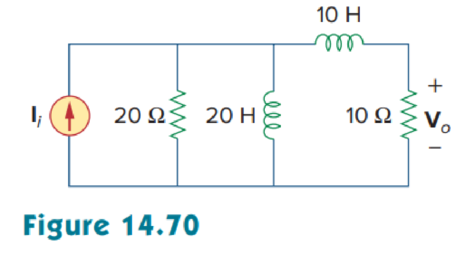
Chapter 14, Problem 3P
For the circuit shown in Fig. 14.70, find H(s) = V0(s)/Ii(s).
Expert Solution & Answer
Want to see the full answer?
Check out a sample textbook solution
Students have asked these similar questions
3. Describe the function of PLL circuit.
4. Describe the function of bandpass filter.
ASK Modulator/Demodulator
U1
VD Signal in
VT out
X1
W
R1
VC Carrier in
w
x2
100K
3
Y1
4
Y2 AD633 Z
VR1
10K
VR1
Multiplier(1)
I
U2
Vx out
X1
W
R3
2
w
x2
In2
100K
3
۲۱
I
Y2 AD633
Z
VR2
R2
10K
C4
100K
VR2
Multiplier(2)
+5V
200p
R5
R6
R101K
ww w
2.7K
22K
1N4148
D1
559
VE out
D+
In(ac)
6 0H
200p
HH
6
VLP out
Vo out
U3
VR
0.01
0.1u
R8
VR3
ww
50K
Envelope Detector
10K
U3
LF356
VR3
LPF
U4Σ
LM311
Comparator
U5
PLL in CS
HH
14 SIGN IN
0.1u
6 CIA
PC1OUT 2
PULSES
PHASE(2)
COMPARATOR OUT 13.
C10
HT
150p R16
ww
R12
VSO
C6
200p
VCO OUT 4
IK
in
R14
C9
18K
10 O
w
7 Cle
H
VLO out
6
15K
VCO
150p
06
11 R1
CD4046
VCO IN 9
VR5
1K
12 R2
0.0047u
C7
I
Demod
C8 out
10
SOURCE
FOLLOWER
R11
100K
INH
COMP IN
5
3
VR4
+5V+12V GND-12V
о
HTO
0.1u
R13
10K
I
PL
VR5
Figure 18-10 KL-94005 module
R15
U6Σ
OP37
BPF
DUC
1. Is the waveform on VT out terminal an ASK modulated signal?
TS
PROD
2. Is the waveform on VT out terminal an OOK modulated signal?
ASK Modulator/Demodulator
U1
VD Signal in
VT out
X1
W
R1
VC Carrier in
w
x2
100K
3
Y1
4
Y2 AD633 Z
VR1
10K
VR1
Multiplier(1)
I
U2
Vx out
X1
W
R3
2
w
x2
In2
100K
3
۲۱
I
Y2 AD633
Z
VR2
R2
10K
C4
100K
VR2
Multiplier(2)
+5V
200p
R5
R6
R101K
ww w
2.7K
22K
1N4148
D1
559
VE out
D+
In(ac)
6 0H
200p
HH
6
VLP out
Vo out
U3
VR
0.01
0.1u
R8
VR3
ww
50K
Envelope Detector
10K
U3
LF356
VR3
LPF
U4Σ
LM311
Comparator
U5
PLL in CS
HH
14 SIGN IN
PC1OUT 2
0.1u
6 CIA
PULSES
PHASE(2)
COMPARATOR
OUT 13
C10
HT
150p R16
ww
R12
VSO
18K
C6
200p
VCO OUT 4
IK
in
R14
C9
10 O
w
H
VLO out
6
7 Cle
15K
VCO
150p
06
11 R1
CD4046
VCO IN 9
VR5
1K
12 R2
0.0047u
C7
I
Demod
C8 out
10
SOURCE
FOLLOWER
R11
100K
INH
COMP IN
5
3
VR4
+5V+12V GND-12V
о
HTO
0.1u
R13
10K
I
PL
Figure 18-10 KL-94005 module
VR5
R15
U6Σ
OP37
BPF
h
e
6. Discuss the relationship between Vx out and VLP out signals.
7. Describe the function of comparator.
ASK Modulator/Demodulator
U1
VD Signal in
VT out
X1
W
R1
VC Carrier in
w
x2
100K
3
Y1
4
Y2 AD633 Z
VR1
10K
VR1
Multiplier(1)
I
U2
Vx out
X1
W
R3
2
w
x2
In2
100K
3
۲۱
I
Y2 AD633
Z
VR2
R2
10K
C4
100K
VR2
Multiplier(2)
+5V
200p
R5
R6
R101K
ww w
2.7K
22K
1N4148
D1
559
VE out
D+
In(ac)
6 0H
200p
HH
6
VLP out
Vo out
U3
VR
0.01
0.1u
R8
VR3
ww
50K
Envelope Detector
10K
U3
LF356
VR3
LPF
U4Σ
LM311
Comparator
U5
PLL in CS
HH
14 SIGN IN
0.1u
6 CIA
PC1OUT 2
PULSES
PHASE(2)
COMPARATOR OUT 13.
C10
HT
150p R16
ww
R12
VSO
C6
200p
VCO OUT 4
IK
in
R14
C9
18K
10 O
w
7 Cle
H
VLO out
6
15K
VCO
150p
06
11 R1
CD4046
VCO IN 9
VR5
1K
12 R2
0.0047u
C7
I
Demod
C8 out
10
SOURCE
FOLLOWER
R11
100K
INH
COMP IN
5
3
VR4
+5V+12V GND-12V
о
HTO
0.1u
R13
10K
I
PL
VR5
Figure 18-10 KL-94005 module
R15
U6Σ
OP37
BPF
Chapter 14 Solutions
Fundamentals of Electric Circuits
Ch. 14.2 - Obtain the transfer function VoVs of the RL...Ch. 14.2 - Prob. 2PPCh. 14.4 - Draw the Bode plots for the transfer function...Ch. 14.4 - Sketch the Bode plots for H()=50j(j+4)(j+10)2Ch. 14.4 - Construct the Bode plots for H(s)=10s(s2+80s+400)Ch. 14.4 - Obtain the transfer function H() corresponding to...Ch. 14.5 - A series-connected circuit has R = 4 and L = 25...Ch. 14.6 - A parallel resonant circuit has R = 100 k, L = 50...Ch. 14.6 - Calculate the resonant frequency of the circuit in...Ch. 14.7 - For the circuit in Fig. 14.40, obtain the transfer...
Ch. 14.7 - Design a band-pass filter of the form in Fig....Ch. 14.8 - Design a high-pass filter with a high-frequency...Ch. 14.8 - Design a notch filter based on Fig. 14.47 for 0 =...Ch. 14.9 - Prob. 14PPCh. 14.10 - Obtain the frequency response of the circuit in...Ch. 14.10 - Consider the network in Fig. 14.57. Use PSpice to...Ch. 14.12 - For an FM radio receiver, the incoming wave is in...Ch. 14.12 - Repeat Example 14.18 for band-pass filter BP6....Ch. 14.12 - If each speaker in Fig. 14.66 has an 8- resistance...Ch. 14 - Prob. 1RQCh. 14 - On the Bode magnitude plot, the slope of 1/5+j2...Ch. 14 - On the Bode phase plot for 0.5 50, the slope of...Ch. 14 - How much inductance is needed to resonate at 5 kHz...Ch. 14 - The difference between the half-power frequencies...Ch. 14 - Prob. 6RQCh. 14 - Prob. 7RQCh. 14 - Prob. 8RQCh. 14 - What kind of filter can be used to select a signal...Ch. 14 - A voltage source supplies a signal of constant...Ch. 14 - Find the transfer function Io/Ii of the RL circuit...Ch. 14 - Using Fig. 14.69, design a problem to help other...Ch. 14 - For the circuit shown in Fig. 14.70, find H(s) =...Ch. 14 - Find the transfer function H(s) = Vo/Vi of the...Ch. 14 - For the circuit shown in Fig. 14.72, find H(s) =...Ch. 14 - For the circuit shown in Fig. 14.73, find H(s) =...Ch. 14 - Calculate |H()| if HdB equals (a) 0.1 dB (b) 5 dB...Ch. 14 - Design a problem to help other students calculate...Ch. 14 - A ladder network has a voltage gain of...Ch. 14 - Design a problem to help other students better...Ch. 14 - Sketch the Bode plots for H()=0.2(10+j)j(2+j)Ch. 14 - A transfer function is given by...Ch. 14 - Construct the Bode plots for...Ch. 14 - Draw the Bode plots for H()=250(j+1)j(2+10j+25)Ch. 14 - Prob. 15PCh. 14 - Sketch Bode magnitude and phase plots for...Ch. 14 - Sketch the Bode plots for G(s)=s(s+2)2(s+1), s = jCh. 14 - A linear network has this transfer function...Ch. 14 - Sketch the asymptotic Bode plots of the magnitude...Ch. 14 - Design a more complex problem than given in Prob....Ch. 14 - Sketch the magnitude Bode plot for...Ch. 14 - Find the transfer function H() with the Bode...Ch. 14 - The Bode magnitude plot of H() is shown in Fig....Ch. 14 - The magnitude plot in Fig. 14.76 represents the...Ch. 14 - A series RLC network has R = 2 k, L = 40 mH, and C...Ch. 14 - Design a problem to help other students better...Ch. 14 - Design a series RLC resonant circuit with 0 = 40...Ch. 14 - Design a series RLC circuit with B = 20 rad/s and...Ch. 14 - Let vs = 20 cos(at) V in the circuit of Fig....Ch. 14 - A circuit consisting of a coil with inductance 10...Ch. 14 - Design a parallel resonant RLC circuit with 0 =...Ch. 14 - Design a problem to help other students better...Ch. 14 - A parallel resonant circuit with a bandwidth of 40...Ch. 14 - A parallel RLC circuit has R = 100 k, L = 100 mH,...Ch. 14 - A parallel RLC circuit has R = 10 k, L = 100 mH,...Ch. 14 - It is expected that a parallel RLC resonant...Ch. 14 - Rework Prob. 14.25 if the elements are connected...Ch. 14 - Find the resonant frequency of the circuit in Fig....Ch. 14 - For the tank circuit in Fig. 14.79, find the...Ch. 14 - Prob. 40PCh. 14 - Using Fig. 14.80, design a problem to help other...Ch. 14 - For the circuits in Fig. 14.81, find the resonant...Ch. 14 - Calculate the resonant frequency of each of the...Ch. 14 - For the circuit in Fig. 14.83, find: (a) the...Ch. 14 - For the circuit shown in Fig. 14.84. find 0, B,...Ch. 14 - For the network illustrated in Fig. 14.85, find...Ch. 14 - Prob. 47PCh. 14 - Find the transfer function Vo/Vs of the circuit in...Ch. 14 - Design a problem to help other students better...Ch. 14 - Determine what type of filter is in Fig. 14.87....Ch. 14 - Design an RL low-pass filter that uses a 40-mH...Ch. 14 - Design a problem to help other students better...Ch. 14 - Design a series RLC type band-pass filter with...Ch. 14 - Design a passive band-stop filter with 0 = 10...Ch. 14 - Determine the range of frequencies that will be...Ch. 14 - (a) Show that for a band-pass filter,...Ch. 14 - Determine the center frequency and bandwidth of...Ch. 14 - The circuit parameters for a series RLC band-stop...Ch. 14 - Find the bandwidth and center frequency of the...Ch. 14 - Obtain the transfer function of a high-pass filter...Ch. 14 - Find the transfer function for each of the active...Ch. 14 - The filter in Fig. 14.90(b) has a 3-dB cutoff...Ch. 14 - Design an active first-order high-pass filter with...Ch. 14 - Obtain the transfer function of the active filter...Ch. 14 - A high-pass filter is shown in Fig. 14.92. Show...Ch. 14 - A general first-order filter is shown in Fig....Ch. 14 - Design an active low-pass filter with dc gain of...Ch. 14 - Design a problem to help other students better...Ch. 14 - Design the filter in Fig. 14.94 to meet the...Ch. 14 - A second-order active filter known as a...Ch. 14 - Use magnitude and frequency scaling on the circuit...Ch. 14 - Design a problem to help other students better...Ch. 14 - Calculate the values of R, L, and C that will...Ch. 14 - Prob. 74PCh. 14 - In an RLC circuit, R = 20 , L = 4 H, and C = 1 F....Ch. 14 - Given a parallel RLC circuit with R = 5 k, L = 10...Ch. 14 - A series RLC circuit has R = 10 , 0 = 40 rad/s,...Ch. 14 - Redesign the circuit in Fig. 14.85 so that all...Ch. 14 - Refer to the network in Fig. 14.96. (a) Find...Ch. 14 - (a) For the circuit in Fig. 14.97, draw the new...Ch. 14 - The circuit shown in Fig. 14.98 has the impedance...Ch. 14 - Scale the low-pass active filter in Fig. 14.99 so...Ch. 14 - The op amp circuit in Fig. 14.100 is to be...Ch. 14 - Using PSpice or MultiSim, obtain the frequency...Ch. 14 - Use PSpice or MultiSim to obtain the magnitude and...Ch. 14 - Using Fig. 14.103, design a problem to help other...Ch. 14 - In the interval 0.1 f 100 Hz, plot the response...Ch. 14 - Use PSpice or MultiSim to generate the magnitude...Ch. 14 - Obtain the magnitude plot of the response Vo in...Ch. 14 - Obtain the frequency response of the circuit in...Ch. 14 - For the tank circuit of Fig. 14.79, obtain the...Ch. 14 - Using PSpice or MultiSim, plot the magnitude of...Ch. 14 - For the phase shifter circuit shown in Fig....Ch. 14 - For an emergency situation, an engineer needs to...Ch. 14 - A series-tuned antenna circuit consists of a...Ch. 14 - The crossover circuit in Fig. 14.108 is a low-pass...Ch. 14 - The crossover circuit in Fig. 14.109 is a...Ch. 14 - A certain electronic test circuit produced a...Ch. 14 - In an electronic device, a series circuit is...Ch. 14 - In a certain application, a simple RC low-pass...Ch. 14 - In an amplifier circuit, a simple RC high-pass...Ch. 14 - Practical RC filter design should allow for source...Ch. 14 - The RC circuit in Fig. 14.111 is used for a lead...Ch. 14 - A low-quality-factor, double-tuned band-pass...
Knowledge Booster


Learn more about
Need a deep-dive on the concept behind this application? Look no further. Learn more about this topic, electrical-engineering and related others by exploring similar questions and additional content below.Similar questions
- Choose one of the choices indicated in the parentheses such as the following sentences have correct messing What is the main purpose of a communication system? a) To transmit information from one point to another b) To amplify signals for better reception c) To filter out unwanted noise dy To generate carrier waves for modulation 2. What the purpose of the modulator in a communication system? a) To generate the cares wave for modulation b) To convert the information signal to a modulated signal c) To filter out unwanted noise d) To amplify the modulated signal for transmission Which component in an FM transmitter is responsible for generating the carrier signal? a) Mixer b) Modulator c) Demodulator d) Oscillator 4 For a FM signal v(t) 25 cos (15 deviation 10 (3456 4 24669, 7321 7.21284) 117 10 sm 15501). Maximum frequency 5. In an AM receiver, which component is responsible for separating the modulating signal from the received AM signal? a) Mixer b) Modulator c) Demodulator dy…arrow_forwardQ1. Choose the correct answer: 1. Increasing the amplitude of a square pulse (increases, decreases, maintains not related) the spectrum range in the frequency domain. 2. A continuous FT indicates a signal. (continuous, discrete, periodic non-periodic). the pulse duration is proportional to the amplitude of the signal. (PAM, PWM, PPM, 3. In ASK). . In VSB transmission (both sidebands are used, single sideband is used, single sideband and part of the other sideband, only the vestige of the carrier signal is used). 5. An economic FDM receiver design should contain simultaneous reception, selective reception). 6. In AMI code, the shapes of "1" and "0" are dependent, not related to each other). 7. In FDM the guard band is used to (pilot carrier zero crossing detector, (the same) opposite to each other, next bit increase the overlap between FDM signals, decrease the overlap between FDM signals, increase the baseband bandwidth, decrease the baseband bandwidth). 20 3. Higher number of levels…arrow_forwardIn a railway system with a power source of 600 VDC, I need to achieve a load output of 120 VDC for railway lights. I found a DC-DC converter capable of stepping down 600 VDC to 125 VDC. To obtain 120 VDC from this converter, we can use a voltage divider with the following equation: [R2/(R2+R1)]=120/125=0.96=0.96However, using resistors to achieve the desired output voltage raises some concerns. Is it advisable to use railway-grade resistors for this application? I found some resistors in the range of 1-10k ohms, but I am unsure how they should be connected in the circuit with the lights (the load to be used). I would greatly appreciate any suggestions or schematic diagrams to clarify the best approach for connecting the resistors in this setup.arrow_forward
- Find the valve of the voltage Vx using the THEVENIN equivalent circuit and redo the problem with the NORTON equivalent circuit. Show both the the vinen and Norton circuits. I 12V m 1 ww 3 23 + 43Vx 5 63 миarrow_forwardFind the valve of V using the Thevenin Equivalent Circuit and then determine if the 8 ohm resistor allows maximum power transfer. If not, then what value should the 8 ohm resistor be changed to for maximum power transfer? ZA 6 6 + 22V 83 V 34 2 6 АААА ААААarrow_forwardFind the valve of voltage Vx using the THE VIN IN equivalent circuit ww 8 Show the Theven in Circuit. I 7V ZV m 6 5 M + 4 34 АА 3 1 АААА 9A ↑ 24arrow_forward
arrow_back_ios
SEE MORE QUESTIONS
arrow_forward_ios
Recommended textbooks for you
 Introductory Circuit Analysis (13th Edition)Electrical EngineeringISBN:9780133923605Author:Robert L. BoylestadPublisher:PEARSON
 Delmar's Standard Textbook Of ElectricityElectrical EngineeringISBN:9781337900348Author:Stephen L. HermanPublisher:Cengage Learning
 Programmable Logic ControllersElectrical EngineeringISBN:9780073373843Author:Frank D. PetruzellaPublisher:McGraw-Hill Education
 Fundamentals of Electric CircuitsElectrical EngineeringISBN:9780078028229Author:Charles K Alexander, Matthew SadikuPublisher:McGraw-Hill Education
 Electric Circuits. (11th Edition)Electrical EngineeringISBN:9780134746968Author:James W. Nilsson, Susan RiedelPublisher:PEARSON
 Engineering ElectromagneticsElectrical EngineeringISBN:9780078028151Author:Hayt, William H. (william Hart), Jr, BUCK, John A.Publisher:Mcgraw-hill Education,
Introductory Circuit Analysis (13th Edition)
Electrical Engineering
ISBN:9780133923605
Author:Robert L. Boylestad
Publisher:PEARSON
Delmar's Standard Textbook Of Electricity
Electrical Engineering
ISBN:9781337900348
Author:Stephen L. Herman
Publisher:Cengage Learning
Programmable Logic Controllers
Electrical Engineering
ISBN:9780073373843
Author:Frank D. Petruzella
Publisher:McGraw-Hill Education
Fundamentals of Electric Circuits
Electrical Engineering
ISBN:9780078028229
Author:Charles K Alexander, Matthew Sadiku
Publisher:McGraw-Hill Education
Electric Circuits. (11th Edition)
Electrical Engineering
ISBN:9780134746968
Author:James W. Nilsson, Susan Riedel
Publisher:PEARSON
Engineering Electromagnetics
Electrical Engineering
ISBN:9780078028151
Author:Hayt, William H. (william Hart), Jr, BUCK, John A.
Publisher:Mcgraw-hill Education,
Why Use Bode Plots? | Understanding Bode Plots, Part 1; Author: MATLAB;https://www.youtube.com/watch?v=F6-EaZobHNk;License: Standard Youtube License