Videos
Repeat Prob. 14-60. but at a water temperature of 80°C. Repeat for 90°C. Discuss.
The maximum volume flow rate at which cavitation occur.
Answer to Problem 61P
The maximum volume flow rate at which cavitation occur is
Explanation of Solution
Given information:
The temperature of the water is
Write the expression for the required head using the energy balance equation.
Here, the initial pressure is
Write expression for the available net positive suction head at the pump inlet.
Here, the saturation pressure is
Write the expression for the minor losses.
Here, the minor loss coefficient due to sharp edge is
Write the expression for the velocity of the water.
Write the expression for the Reynolds number.
Here, the density of the water is
Write the expression for the minor losses.
Write the expression for the required net positive suction head.
Write the expression for the friction factor.
Here, the friction factor is
Calculation:
Refer to the Table-A-7E, "Properties of saturated liquid" to obtain the density of the water as
Substitute
Substitute
Use hit and trial method to obtain the volume flow rate.
Iteration 1 consider the volume flow rate as
Substitute
Substitute
Substitute
Substitute
Substitute
Since, the available net positive suction head is greater than the required net positive suction head hence, cavitation does not occur at this flow rate.
The different iteration are shown in the below Table.
| S.No | |||
| 1 | |||
| 2 | |||
| 3 | |||
| 4 | |||
| 5 | |||
| 6 | |||
| 7 | |||
Draw the plot between the flow rate and available net positive suction head and the required net positive suction head.
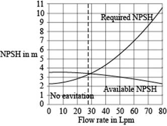
Figure-(1)
Figure-(1) shows that the cavitation occur at volume flow rates above the
Refer to the Table-A-7E, "Properties of saturated liquid" to obtain the density of the water as
Substitute
Substitute
Use hit and trial method to obtain the volume flow rate.
Iteration 1 consider the volume flow rate as
Substitute
Substitute
Substitute
Substitute
Substitute
Since, the available net positive suction head is greater than the required net positive suction head hence, cavitation does not occur at this flow rate.
The different iteration are shown in the below Table.
| S.No | |||
| 1 | |||
| 2 | |||
| 3 | |||
| 4 | |||
| 5 | |||
| 6 |
Draw the plot between the flow rate and available net positive suction head and the required net positive suction head.
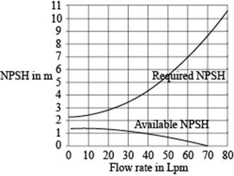
Figure-(2)
From Figure-(2), available net positive suction head and the required net positive suction head curves are not crossing each other as the temperature of water is near to boiling temperature. The pump cavitates at any flow rate.
Conclusion:
The maximum volume flow rate at which cavitation occurs is
Want to see more full solutions like this?
Chapter 14 Solutions
Fluid Mechanics: Fundamentals and Applications


- For the walking-beam mechanism shown in Figure 3, find and plot the x and y coordinates of the position of the coupler point P for one complete revolution of the crank O2A. Use the coordinate system shown in Figure 3. Hint: Calculate them first with respect to the ground link 0204 and then transform them into the global XY coordinate system. y -1.75 Ꮎ Ꮎ 4 = 2.33 0242.22 L4 x AP = 3.06 L2 = 1.0 W2 31° B 03 L3 = 2.06 P 1 8 5 .06 6 7 P'arrow_forwardThe link lengths, gear ratio (2), phase angle (Ø), and the value of 02 for some geared five bar linkages are defined in Table 2. The linkage configuration and terminology are shown in Figure 2. For the rows assigned, find all possible solutions for angles 03 and 04 by the vector loop method. Show your work in details: vector loop, vector equations, solution procedure. Table 2 Row Link 1 Link 2 Link 3 Link 4 Link 5 λ Φ Ө a 6 1 7 9 4 2 30° 60° P y 4 YA B b R4 R3 YA A Gear ratio: a 02 d 05 r5 R5 R2 Phase angle: = 0₂-202 R1 05 02 r2 Figure 2. 04 Xarrow_forwardProblem 4 A .025 lb bullet C is fired at end B of the 15-lb slender bar AB. The bar is initially at rest, and the initial velocity of the bullet is 1500 ft/s as shown. Assuming that the bullet becomes embedded in the bar, find (a) the angular velocity @2 of the bar immediately after impact, and (b) the percentage loss of kinetic energy as a result of the impact. (c) After the impact, does the bar swing up 90° and reach the horizontal? If it does, what is its angular velocity at this point? Answers: (a). @2=1.6 rad/s; (b). 99.6% loss = (c). Ah2 0.212 ft. The bar does not reach horizontal. y X 4 ft 15 lb V₁ 1500 ft/s 0.025 lb C 30°7 B Aarrow_forward
- subject: combustion please include complete solution, no rounding off, with diagram/explanation etc. In a joule cycle, intake of the compressor is 40,000 cfm at 0.3 psig and 90 deg F. The compression ratio is 6.0 and the inlet temperature at the turbine portion is 1900R while at the exit, it is 15 psi. Calculate for the back work ratio in percent.arrow_forwardsubject: combustion please include complete solution, no rounding off, with diagram/explanation etc. A gasoline engine, utilizing cold air, recorded a work of 431 BTU/lb at a maximum temperature of 3,273 K and 1112 deg F temperature at the beginning of constant volume heat addition. What is the compression ratio?arrow_forwardsubject: combustion please do step by step solution and no rounding off, complete solution with diagram/explanation if needed etc. thank you! Air enters the compressor at 101,320 Pascals, 305.15K, and leaves at a pressure of 0.808MPa. The air is heated to 990.15K in the combustion chamber. For a net output of 2,125,000 Watts, find the rate of flow of air per second.arrow_forward
- The link lengths and the value of 2 and offset for some fourbar crank-slide linkages are defined in Table 1. The linkage configuration and terminology are shown in Figure 1. For the rows assigned, find (a) all possible solutions for angle & and slider position d by vector loop method. (b) the transmission angle corresponding to angle 03. (Hint: Treat the vector R4 as virtual rocker) Show your work in details: vector loop, vector equations, solution procedure. Table 1 Row Link 2 Link 3 Offset Ө a 1.4 4 1 45° b 3 8 2 -30° C 5 20 -5 225° 03 slider axis B X offset Link 2 A R3 Link 3 R4 04 R2 02 R1 d Figure 1. Xarrow_forward4. Two links made of heat treated 6061 aluminum (Sy = 276 MPa, Sys = 160 MPa) are pinned together using a steel dowel pin (Sy = 1398 MPa, Sys = 806 MPa) as shown below. The links are to support a load P with a factor of safety of at least 2.0. Determine if the link will fail first by tearout, direct shear of the pin, bearing stress on the link, or tensile stress at section AA. (Hint: find the load P for each case and choose the case that gives the smallest load.) P 8 mm P 8 mm ¡+A 3 mm →A 10 mm Parrow_forward1. For a feature other than a sphere, circularity is where: A. The axis is a straight line B. The modifier is specified with a size dimension C. All points of the surface intersected by any plane perpendicular to an axis or spine (curved line) are equidistant from that axis or spine D. All points of the surface intersected by any plane passing through a common center are equidistant from that center 2. What type of variation is limited by a circularity toler- ance zone? A. Ovality B. Tapering C. Bending D. Warping 3. How does the Rule #1 boundary affect the application of a circularity tolerance? A. The modifier must be used. B. The feature control frame must be placed next to the size dimension. C. The circularity tolerance value must be less than the limits of size tolerance. D. Circularity cannot be applied where a Rule #1 boundary exists. 4. A circularity tolerance may use a modifier. A. Ø B. F C. M D. ℗ 5. A real-world application for a circularity tolerance is: A. Assembly (i.e.,…arrow_forward
- 3. A steel bar is pinned to a vertical support column by a 10 mm diameter hardened dowel pin, Figure 1. For P = 7500 N, find: a. the shear stress in the pin, b. the direct bearing stress on the hole in the bar, c. the minimum value of d to prevent tearout failure if the steel bar has a shear strength of 175 MPa. support column pin bar thickness of bar = 8 mm h d 150 mmarrow_forwardA press that delivers 115 strokes per minute, each stroke providing a force of 7826 N throughout a distance of 18 mm. The press efficiency is 90% and is driven by a 1749-rpm motor. Determine average torque that must be provided by the motor in the units of N-m.arrow_forward·3) find the force (P) for the figures (1) and (2) 15cm 10cm 15 h=10mm h2=6mm // Call = 90 N/2 P Agate Fig (i) Ans: 1)P=112614N 2) P=1956.5 N 25cm 25 cm الفترة أو الحجم تمر بالتي عثر اكو تورشن (ک Fig (2) h₁ = 10mm 42=6mm Cmarrow_forward
 Principles of Heat Transfer (Activate Learning wi...Mechanical EngineeringISBN:9781305387102Author:Kreith, Frank; Manglik, Raj M.Publisher:Cengage Learning
 Refrigeration and Air Conditioning Technology (Mi...Mechanical EngineeringISBN:9781305578296Author:John Tomczyk, Eugene Silberstein, Bill Whitman, Bill JohnsonPublisher:Cengage Learning