Concept explainers
Videos
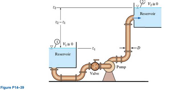
A water pump is used to pump water from one large reservoir to another large reservoir that is at a higher elevation. The free surfaces of both reservoirs are exposed to atmospheric pressure, as sketched in Fig. P 14-39. The dimensions and minor loss coefficients are provided in the figure. The pump' s performance is approximated by the expression
The volume capacity delivered by the pump.
Answer to Problem 43P
The volume capacity delivered by the pump is
Explanation of Solution
Given information:
The diameter of pipe is
Write the expression for head required.
Here, pressure at exit is
Write the expression for coefficient of total minor head loss.
Here, coefficient of entrance loss is
Write the expression for head loss.
Here, length of pipe is
Write the expression for
Here, shutoff head is
Write the expression for Reynolds number.
Here, density of water is
Write the expression for Colebrook equation.
Here, coefficient of friction is
Write the expression for volume flow rate.
Calculation:
Substitute
Substitute
Substitute
Substitute
Refer Table-A-3 "Properties of saturated water" at
Substitute
Substitute
Substitute
Here, apply hit and trial method to calculate the velocity of flow.
Trial-(1)
Substitute
Since the value on both sides are not equal, so assumption of
Trial-(2)
Substitute
Here, the values on both sides are equal, so assumption is correct and velocity of flow is
Substitute
Conclusion:
The volume capacity delivered by the pump is
Want to see more full solutions like this?
Chapter 14 Solutions
Fluid Mechanics Fundamentals And Applications


- Procedure:1- Cartesian system, 2D3D,type of support2- Free body diagram3 - Find the support reactions4- If you find a negativenumber then flip the force5- Find the internal force3D∑Fx=0∑Fy=0∑Fz=0∑Mx=0∑My=0\Sigma Mz=02D\Sigma Fx=0\Sigma Fy=0\Sigma Mz=05- Use method of sectionand cut the elementwhere you want to findthe internal force andkeep either side of thearrow_forwardProcedure: 1- Cartesian system, 2(D)/(3)D, type of support 2- Free body diagram 3 - Find the support reactions 4- If you find a negative number then flip the force 5- Find the internal force 3D \sum Fx=0 \sum Fy=0 \sum Fz=0 \sum Mx=0 \sum My=0 \Sigma Mz=0 2D \Sigma Fx=0 \Sigma Fy=0 \Sigma Mz=0 5- Use method of section and cut the element where you want to find the internal force and keep either side of the sectionarrow_forwardProcedure: 1- Cartesian system, 2(D)/(3)D, type of support 2- Free body diagram 3 - Find the support reactions 4- If you find a negative number then flip the force 5- Find the internal force 3D \sum Fx=0 \sum Fy=0 \sum Fz=0 \sum Mx=0 \sum My=0 \Sigma Mz=0 2D \Sigma Fx=0 \Sigma Fy=0 \Sigma Mz=0 5- Use method of section and cut the element where you want to find the internal force and keep either side of the sectionarrow_forward
- For each system below with transfer function G(s), plot the pole(s) on the s-plane. and indicate whether the system is: (a) "stable" (i.e., a bounded input will always result in a bounded output), (b) "marginally stable," or (c) "unstable" Sketch a rough graph of the time response to a step input. 8 a) G(s) = 5-5 8 b) G(s) = c) G(s) = = s+5 3s + 8 s² - 2s +2 3s +8 d) G(s): = s²+2s+2 3s+8 e) G(s): = s² +9 f) G(s): 8 00 == Sarrow_forwardPlease answer the following question. Include all work and plase explain. Graphs are provided below. "Consider the Mg (Magnesium) - Ni (Nickel) phase diagram shown below. This phase diagram contains two eutectic reactions and two intermediate phases (Mg2Ni and MgNi2). At a temperature of 505oC, determine what the composition of an alloy would need to be to contain a mass fraction of 0.20 Mg and 0.80 Mg2Ni."arrow_forwardThe triangular plate, having a 90∘∘ angle at AA, supports the load PP = 370 lblb as shown in (Figure 1).arrow_forward
- Design a 4-bar linkage to carry the body in Figure 1 through the two positions P1 and P2 at the angles shown in the figure. Use analytical synthesis with the free choice values z = 1.075, q= 210°, ß2 = −27° for left side and s = 1.24, y= 74°, ½ = − 40° for right side. φ 1.236 P2 147.5° 210° 2.138 P1 Figure 1 Xarrow_forwardDesign a 4-bar linkage to carry the body in Figure 1 through the two positions P1 and P2 at the angles shown in the figure. Use analytical synthesis with the free choice values z = 1.075, q= 210°, B₂ = −27° for left side and s = 1.24, y= 74°, ½ = − 40° for right side. 1.236 P2 147.5° 210° P1 Figure 1 2.138 Xarrow_forwardcan you explain how in a coordinate frame transformation: v = {v_n}^T {n-hat} and then it was found that {n-hat} = [C]^T {b-hat} so v_n = {v_n}^T [C]^T {b-hat}, how does that equation go from that to this --> v_n = [C]^T v_barrow_forward
- 6) If (k = 0,7 cm) find Imax for figure below. 225mm 100mm ثلاثاء. 100mm 150mm 75mm Ans: Tmax=45:27 N/cm F-400 Narrow_forwardThe man has a weight W and stands halfway along the beam. The beam is not smooth, but the planes at A and B are smooth (and plane A is horizontal). Determine the magnitude of the tension in the cord in terms of W and θ.arrow_forwardDetermine the reactions at the two supports for this plate. Express the reactions in Cartesian vector form.arrow_forward
 Elements Of ElectromagneticsMechanical EngineeringISBN:9780190698614Author:Sadiku, Matthew N. O.Publisher:Oxford University Press
 Mechanics of Materials (10th Edition)Mechanical EngineeringISBN:9780134319650Author:Russell C. HibbelerPublisher:PEARSON
 Thermodynamics: An Engineering ApproachMechanical EngineeringISBN:9781259822674Author:Yunus A. Cengel Dr., Michael A. BolesPublisher:McGraw-Hill Education
 Control Systems EngineeringMechanical EngineeringISBN:9781118170519Author:Norman S. NisePublisher:WILEY
 Mechanics of Materials (MindTap Course List)Mechanical EngineeringISBN:9781337093347Author:Barry J. Goodno, James M. GerePublisher:Cengage Learning
 Engineering Mechanics: StaticsMechanical EngineeringISBN:9781118807330Author:James L. Meriam, L. G. Kraige, J. N. BoltonPublisher:WILEY