
Applied Statics and Strength of Materials (6th Edition)
6th Edition
ISBN: 9780133840544
Author: George F. Limbrunner, Craig D'Allaird, Leonard Spiegel
Publisher: PEARSON
expand_more
expand_more
format_list_bulleted
Videos
Textbook Question
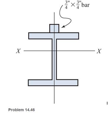
Chapter 14, Problem 14.46SP
A
Expert Solution & Answer
Want to see the full answer?
Check out a sample textbook solution
Students have asked these similar questions
A man skis down a slope. His initial elevation was 150 m and his velocity at the bottom of the slope is 17 m/s. What percentage of his initial potential energy was consumed due to friction and air resistance? Use the accounting equation in your calculations.
In direct calorimetry, a person is placed in a large, water-insulated chamber. The chamber is kept at a constant temperature. While in the chamber, the subject is asked to perform a number of normal activities, such as eating, sleeping, and exercising. The rate of heat released from the subject’s body can be measured by the rate of heat gain by the water bath. Would direct calorimetry be a practical way to measure metabolic rate? Why or why not?A person is placed inside a calorimetric chamber for 24 hours. During this time, the 660-gallon water bath heats up by 3.2°F. What is the subject’s metabolic rate during this period? Report your answer in kcal/day. Assume that there is no heat loss from the water to the surroundings.
Upon reentry into the Earth’s atmosphere, the bottom of a space shuttle heats up to dangerous levels as the craft slows for landing. If the velocity of the shuttle is 28,500 km/hr at the beginning of reentry and 370 km/hr just prior to landing, how much energy is lost as heat? The shuttle has a mass of 90,000 kg. Assume that the change in potential energy is negligible compared to the change in kinetic energy.
Chapter 14 Solutions
Applied Statics and Strength of Materials (6th Edition)
Ch. 14 - Calculate the section modulus for: (a) a 6 -in-by-...Ch. 14 - Calculate the section modulus (with respect to the...Ch. 14 - Prob. 14.3PCh. 14 - Rework Problem 14.3 changing the orientation of...Ch. 14 - Assume that the timber member (a) of Problem 14.2...Ch. 14 - The structural steel built-up member (b) of...Ch. 14 - A round steel rod, 25 mm in diameter, is subjected...Ch. 14 - A square steel bar, 38 mm on each side, is used as...Ch. 14 - Calculate the moment strength for a W36302...Ch. 14 - Calculate the allowable bending moment for a solid...
Ch. 14 - The beams of cross sections shown are subjected to...Ch. 14 - A solid rectangular simply supported timber beam 6...Ch. 14 - A W1430 supports the loads shown. Calculate the...Ch. 14 - If the allowable shear stress is 100 MPa,...Ch. 14 - A steel pin 112 in diameter is subjected to a...Ch. 14 - A timber power-line pole is 10 in. in diameter at...Ch. 14 - Calculate the value of S and Z and the shape...Ch. 14 - For beams that have cross sections as shown for...Ch. 14 - Calculate the maximum load P that the beam shown...Ch. 14 - A 412 (S4S) hem-fir timber beam carries a...Ch. 14 - A simply supported W1636 A992 steel beam carries a...Ch. 14 - A W250115 steel wide-flange section supports a...Ch. 14 - Assume that the floor joist dimensions of Example...Ch. 14 - Calculate the allowable superimposed uniformly...Ch. 14 - A 3 -in.-by- 12 -in. (S4S) scaffold timber plank...Ch. 14 - For the following computer problems, any...Ch. 14 - For the following computer problems, any...Ch. 14 - For the following computer problems, any...Ch. 14 - Calculate the section modulus with respect to the...Ch. 14 - The timber box section (a) of Problem 14.29 is...Ch. 14 - A timber beam is subjected to a maximum bending...Ch. 14 - Rework Problem 14.31 assuming that the beam is...Ch. 14 - A 12 -in.-diameter steel rod projects 2 ft...Ch. 14 - Calculate the maximum bending stress in a W530101...Ch. 14 - A cantilever cast-iron beam is 6 ft long and has a...Ch. 14 - 14.36 Calculate the moment strength for a...Ch. 14 - A W813 steel wide-flange beam on a 20 -ft span is...Ch. 14 - A simply supported beam with a cruciform cross...Ch. 14 - A rectangular beam 100 mm in width and 250 mm in...Ch. 14 - The timber box section (a) of Problem 14.29 is...Ch. 14 - For the I-shaped timber beam shown, calculate the...Ch. 14 - 14.42 A steel wide-flange beam is oriented so that...Ch. 14 - A W1045steel wide-flange beam supports a uniformly...Ch. 14 - 14.44 A steel wide-flange section is subjected to...Ch. 14 - A W30108 steel wide-flange beam is simply...Ch. 14 - A W612 is strengthened with a 34 -in.-by- 34 -in....Ch. 14 - Four wood boards 1 in. by 6 in. in cross section...Ch. 14 - A lintel consists of two 8 -in.-by- 12 in. steel...Ch. 14 - A 50 -mm-by- 300 -mm scaffold timber plank, placed...Ch. 14 - A laminated wood beam is built up by gluing...Ch. 14 - A rectangular hollow shape carries loads as shown....Ch. 14 - For the beam shown, calculate the maximum tensile...Ch. 14 - 14.53 A box beam is built up of four -in.-by--in....Ch. 14 - 14.54 Find the value of the loads P that can be...Ch. 14 - 14.55 Solve Problem 14.54 assuming that the timber...Ch. 14 - Calculate the values of S and Z and the shape...Ch. 14 - 14.57 A is supported on simple supports on a -ft...
Knowledge Booster


Learn more about
Need a deep-dive on the concept behind this application? Look no further. Learn more about this topic, mechanical-engineering and related others by exploring similar questions and additional content below.Similar questions
- of the basket of the balloon at point A, and their other ends are staked to the ground. The hook is located in the geometric center of the basket. The balloon and the air inside it have a combined mass of 3000 kg. You want to determine the resultant of the tension forces in the four cables acting on the hook at point A. It is known that the magnitudes of the tension in the cables are as follows: TAB = 207 N; TAC = 355 N; TAD = 250 N; and TAE = 486 N. B E 2.5 m C E 5.5 m D 2.5 m 3.5 m 1.5 m Using the information provided in the problem, express the force on the hook at point A by cable AC in rectangular component form. The force on the hook at point A by cable AC in rectangular component form is given below. T AC N) i+ N) + N) Rarrow_forwardWater in the glass tube is at a temperature of 40°C. Plot the height of the water as a function of the tube's inner diameter D for 0.5mm≤D≤3mm. Use increments of 0.5mm. Take sigma=69.6mN/m, and theta=0° for the contact angle.arrow_forwardDetermine the distance h that the column of mercury in the tube will be depressed when the tube is inserted into the mercury at a room temperature of 68 F. Plot this relationship of h (vertical axis) versus D for 0.5 in≤D≤0.150in. Give values for increments of ΔD=0.025in. Discuss this resultarrow_forward
- Water is at a temperature of 30 C. Plot the height h of the water as a function of the gap w between the two glass plates for 0.4 mm ≤ w ≤ 2.4 mm. Use increments of 0.4mm. Take sigma=0.0718 N/m.arrow_forwardWhat is the reading on the vernier calipers? 7 6 0 5 10 8arrow_forwardDetermine the moments of the force about the x and the a axes. O 4 m F = {-40i +20j + 10k} N 3 m 6 m aarrow_forward
- 6. A part of the structure for a factory automation system is a beam that spans 30.0 in as shown in Figure P5-6. Loads are applied at two points, each 8.0 in from a support. The left load F₁ = 1800 lb remains constantly applied, while the right load F₂ = 1800 lb is applied and removed fre- quently as the machine cycles. Evaluate the beam at both B and C. A 8 in F₁ = 1800 lb 14 in F2 = 1800 lb 8 in D RA B C 4X2X1/4 Steel tube Beam cross section RDarrow_forward30. Repeat Problem 28, except using a shaft that is rotating and transmitting a torque of 150 N⚫m from the left bear- ing to the middle of the shaft. Also, there is a profile key- seat at the middle under the load.arrow_forward28. The shaft shown in Figure P5-28 is supported by bear- ings at each end, which have bores of 20.0 mm. Design the shaft to carry the given load if it is steady and the shaft is stationary. Make the dimension a as large as pos- sible while keeping the stress safe. Determine the required d = 20mm D = ? R = ?| 5.4 kN d=20mm Length not to scale -a = ?- +а= a = ? + -125 mm- -250 mm- FIGURE P5-28 (Problems 28, 29, and 30)arrow_forward
- 12. Compute the estimated actual endurance limit for SAE 4130 WQT 1300 steel bar with a rectangular cross sec- tion of 20.0 mm by 60 mm. It is to be machined and subjected to repeated and reversed bending stress. A reli- ability of 99% is desired.arrow_forward28. The shaft shown in Figure P5-28 is supported by bear- ings at each end, which have bores of 20.0 mm. Design the shaft to carry the given load if it is steady and the shaft is stationary. Make the dimension a as large as pos- sible while keeping the stress safe. Determine the required d = 20mm D = ? R = ?| 5.4 kN d=20mm Length not to scale -a = ?- +а= a = ? + -125 mm- -250 mm- FIGURE P5-28 (Problems 28, 29, and 30)arrow_forward2. A strut in a space frame has a rectangular cross section of 10.0 mm by 30.0 mm. It sees a load that varies from a tensile force of 20.0 kN to a compressive force of 8.0 kN.arrow_forward
arrow_back_ios
SEE MORE QUESTIONS
arrow_forward_ios
Recommended textbooks for you
 Elements Of ElectromagneticsMechanical EngineeringISBN:9780190698614Author:Sadiku, Matthew N. O.Publisher:Oxford University Press
 Mechanics of Materials (10th Edition)Mechanical EngineeringISBN:9780134319650Author:Russell C. HibbelerPublisher:PEARSON
 Thermodynamics: An Engineering ApproachMechanical EngineeringISBN:9781259822674Author:Yunus A. Cengel Dr., Michael A. BolesPublisher:McGraw-Hill Education
 Control Systems EngineeringMechanical EngineeringISBN:9781118170519Author:Norman S. NisePublisher:WILEY
 Mechanics of Materials (MindTap Course List)Mechanical EngineeringISBN:9781337093347Author:Barry J. Goodno, James M. GerePublisher:Cengage Learning
 Engineering Mechanics: StaticsMechanical EngineeringISBN:9781118807330Author:James L. Meriam, L. G. Kraige, J. N. BoltonPublisher:WILEY
Elements Of Electromagnetics
Mechanical Engineering
ISBN:9780190698614
Author:Sadiku, Matthew N. O.
Publisher:Oxford University Press
Mechanics of Materials (10th Edition)
Mechanical Engineering
ISBN:9780134319650
Author:Russell C. Hibbeler
Publisher:PEARSON
Thermodynamics: An Engineering Approach
Mechanical Engineering
ISBN:9781259822674
Author:Yunus A. Cengel Dr., Michael A. Boles
Publisher:McGraw-Hill Education
Control Systems Engineering
Mechanical Engineering
ISBN:9781118170519
Author:Norman S. Nise
Publisher:WILEY
Mechanics of Materials (MindTap Course List)
Mechanical Engineering
ISBN:9781337093347
Author:Barry J. Goodno, James M. Gere
Publisher:Cengage Learning
Engineering Mechanics: Statics
Mechanical Engineering
ISBN:9781118807330
Author:James L. Meriam, L. G. Kraige, J. N. Bolton
Publisher:WILEY
Differences between Temporary Joining and Permanent Joining.; Author: Academic Gain Tutorials;https://www.youtube.com/watch?v=PTr8QZhgXyg;License: Standard Youtube License